Integrated fabricated combined beam bridge construction method

A construction method and an assembled technology, which are applied in the construction field of integrally assembled composite girder bridges, can solve problems such as poor effectiveness, large-scale lifting equipment and road transportation conditions, and unreasonable stress.

Active Publication Date: 2018-05-22
CHONGQING JIAOTONG UNIVERSITY
View PDF8 Cites 10 Cited by
  • Summary
  • Abstract
  • Description
  • Claims
  • Application Information

AI Technical Summary

Problems solved by technology

[0003] In existing steel-concrete composite girder bridges, shear nails are usually placed on the top of the steel girder, and the connection between the bridge slab and the steel girder is realized through the whole or part of the cast-in-place bridge slab, which cannot be fully assembled. After the bridge slab is connected to the steel girder, prestress is applied to the bridge slab in the negative moment section, and part of the prestress is balanced by the steel girder. unreasonable
[0004] The Chinese patent ZL201310130786.4 titled PCSS shear coupled structure discloses a steel-concrete composite structure, using pre-embedded shear force transfer steel plates on the rib side of the prefabricated bridge slab, and installing the prefabricated bridge slab on the steel girder in place , and apply longitudinal prestress to the bridge slab according to the design requirements, and then weld the pre-embedded shear force transfer steel plate on the rib side of the prefabricated bridge slab and the longitudinal joint formed on the top surface of the steel beam to form a steel-concrete composite beam. The construction of a fully assembled steel-concrete composite girder bridge that does not require cast-in-place concrete, and overcomes the problem of poor effectiveness of prestressing the bridge deck in conventional steel-concrete composite continuous girder bridges
However, this method requires on-site single-sided welding of multiple longitudinal joints along the entire length of the bridge formed by the pre-embedded shear force transfer steel plate on the rib side of the bridge slab and the top surface of the steel girder, resulting in a large amount of welding work on site and difficult to guarantee welding quality , and such a single-sided fillet weld has poor fatigue resistance and has potential safety hazards
In order to carry out the actual construction of the above-mentioned structure, a steel-concrete composite beam bridge and its construction method (invention patent application number: 2016111547567) appeared in which the segmental continuous prefabrication is pushed into place and then connected (invention patent application number: 2016111547567). ——Push it to the bridge pier and put it in place, and then prefabricate the bridge slab segment continuously——Push it to the top surface of the steel girder and put it in place, and then transfer the embedded shear force to the steel plate and the top surface of the steel girder on the rib side of the bridge slab On-site welding of each longitudinal seam of the bridge overcomes the problems existing in the construction of the existing prefabricated bridge: Requirements: A huge prefabrication / storage site; B large lifting equipment and road transportation conditions; C structural joint disease between prefabricated parts Hidden defects
Although there are a series of advantages, the fabrication and installation of the steel girder and the bridge slab must be carried out successively, and cannot be carried out at the same time, which increases the construction period; during the construction stage, there is an unfavorable working condition that the self-weight of the bridge slab is only borne by the steel girder. As a result, the amount of steel used has increased significantly; the on-site welding workload is very large, and the welding quality is difficult to guarantee; at the same time, in order to realize prefabrication and jacking construction, a continuous and rapid prefabrication-jacking construction of bridge deck segments was also invented. Equipment for composite bridges (patent Application number 201611155859.5)

Method used


Image

  • Integrated fabricated combined beam bridge construction method
  • Integrated fabricated combined beam bridge construction method
  • Integrated fabricated combined beam bridge construction method

Examples


Embodiment Construction

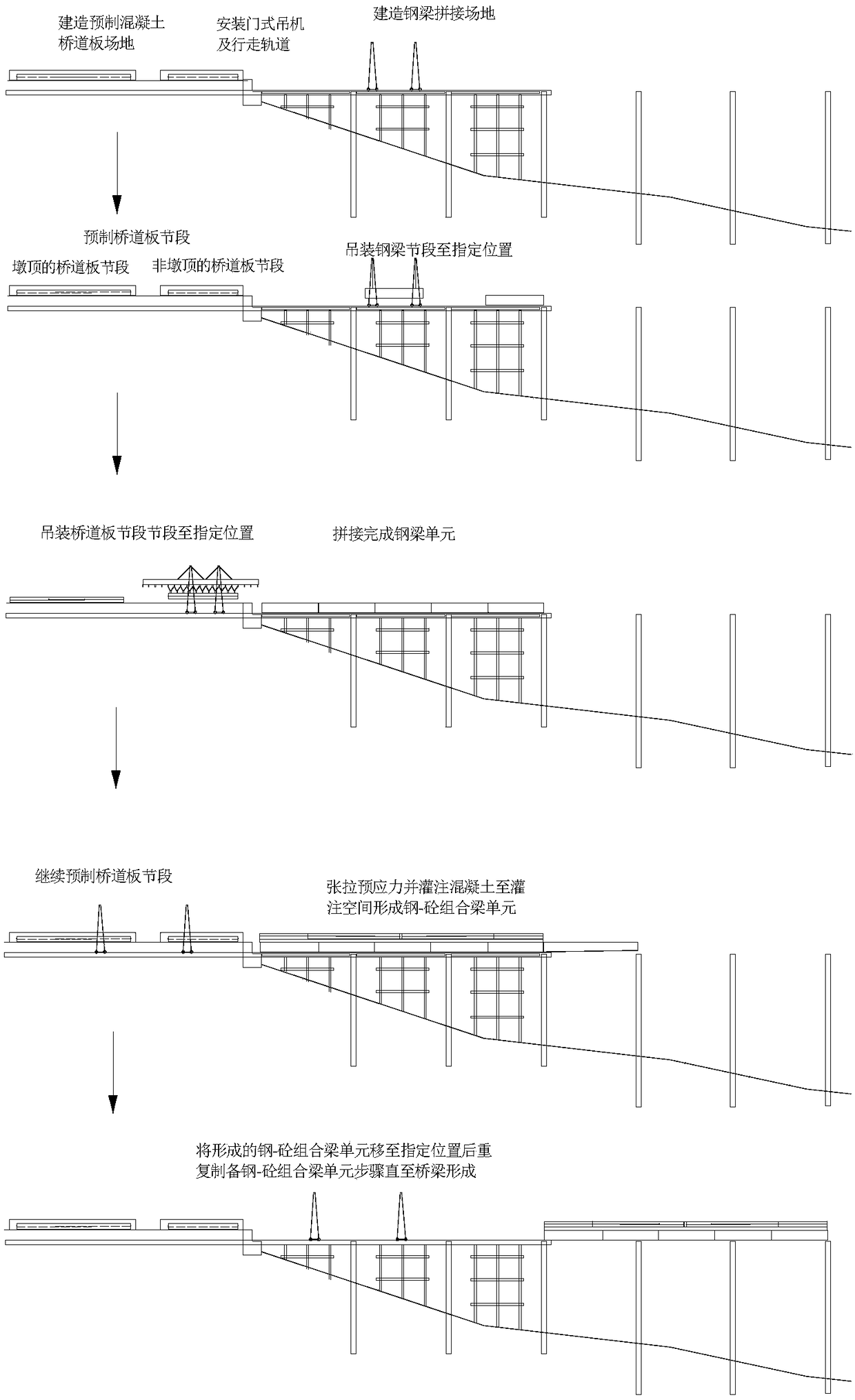
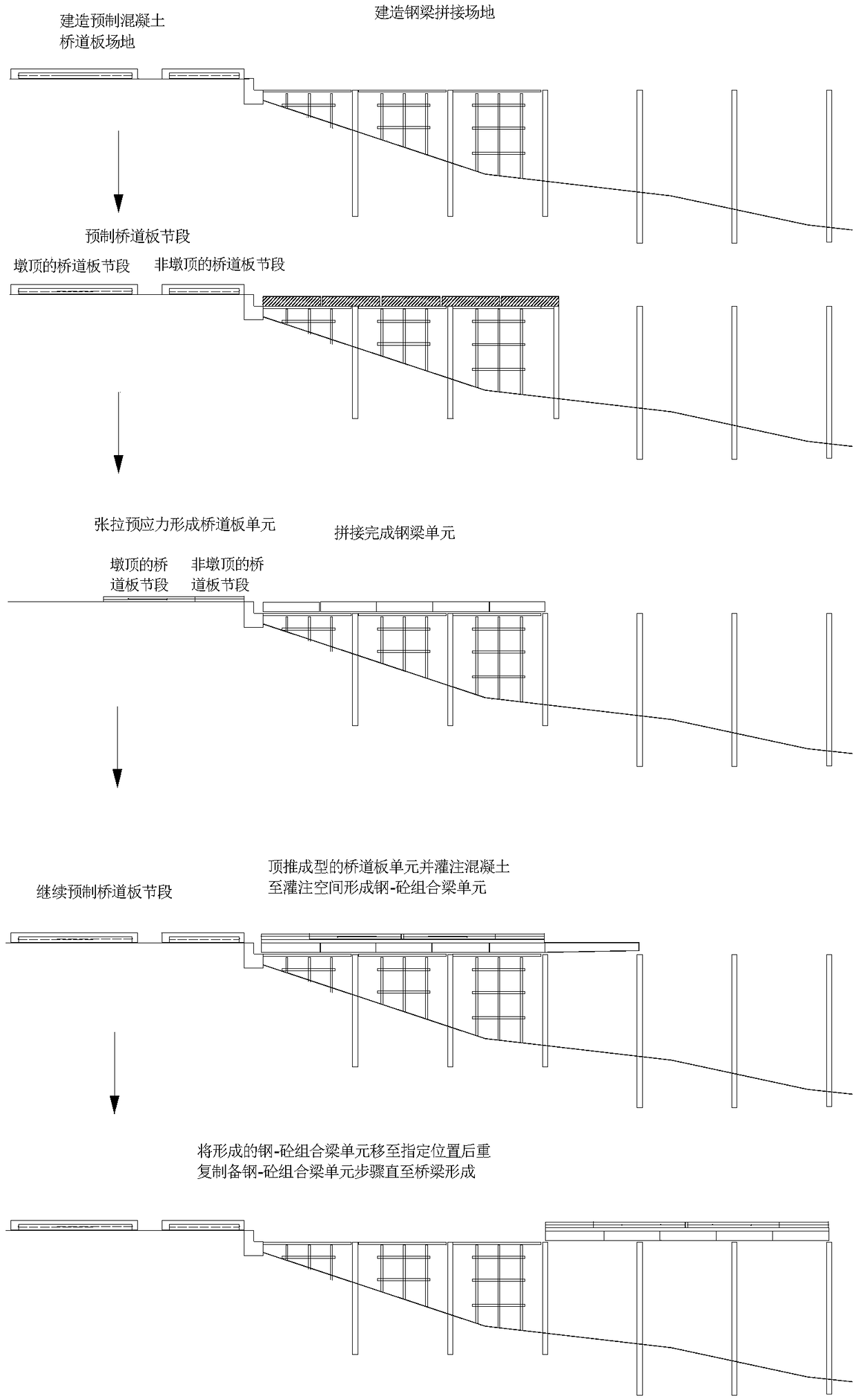
[0038] Such as figure 1 , figure 2 Shown: the present invention also discloses a steel-concrete composite beam bridge factory construction method used in the construction method of the integrally assembled composite beam bridge, comprising the following steps:

[0039] a. Build the prefabricated bridge slab site at a suitable position in front of the bridge head, and build the steel girder splicing site behind the prefabricated bridge slab site; the front of the bridge head refers to the extension direction of the bridge head, and the side toward the middle of the bridge is opposite to the rear; prefabricated bridge The road slab site and the steel girder splicing site are arranged side by side to form a prefabricated bridge head factory that can build the upper structure of the overall steel-concrete composite beam bridge, which is convenient for continuous construction and improves work efficiency. The construction of the site has different constructions according to differ...


PUM


Abstract

The invention discloses an integrated fabricated combined beam bridge construction method. The method comprises the steps that a pushing or lifting prefabricated concrete bridge deck is adopted for being in place on a steel beam, integrated fabricated combination of the whole steel beam unit and the integrated fabricated concrete bridge deck unit is achieved, the integrated steel beam-integrated prefabricated overall width length region concrete bridge deck-integrated bridge deck are formed inside a factory in a splicing mode to the steel beam to be in place, and pressure pouring is performedinside a longitudinal combination cavity to be combined with concrete to form a combination beam-pushing combination beam to move forwards till all the combination beams are in place on correspondingpiers. The brand new construction and implementation scheme is provided for full-factory-like automatic and intelligent combination beam bridge, the obvious defects that the outdoor working is inevitable in existing bridge building and the environment and human factor trouble is caused by manual work are overcome, the actual bridge beam and the design ideal structure are matched, and therefore thebridge later disease potential safety hazards are reduced to the maximum extent.

Description

technical field [0001] The invention belongs to the field of building structures and bridge engineering, in particular to a construction method of an integrally assembled composite girder bridge. Background technique [0002] The steel-concrete composite structure has obvious advantages in terms of material strength, convenient and quick construction, reliable structural performance, and low energy consumption, so it has become more and more the development trend of bridge structures; Therefore, how to connect the two easily and quickly with long-term reliable performance is a problem that the engineering community has been exploring and solving. [0003] In existing steel-concrete composite girder bridges, shear nails are usually placed on the top of the steel girder, and the connection between the bridge slab and the steel girder is realized through the whole or part of the cast-in-place bridge slab, which cannot be fully assembled. After the bridge slab is connected to t...

Claims


Application Information

Patent Timeline
Patent Type & Authority Applications(China)
IPC IPC(8): E01D21/00E01D21/06
Inventor 周志祥周劲宇乔心格
Owner CHONGQING JIAOTONG UNIVERSITY
Why Eureka
Try Eureka