Self tracking method for spacecraft dynamic target by spherical phased array antenna

A phased array antenna and dynamic target technology, applied in the field of aerospace measurement and control, can solve the problems of high-speed moving targets that cannot be captured, impossible target capture, antenna vibration and prolonged convergence adjustment time, etc., to achieve less resource occupation and reliability High, simple effect

Inactive Publication Date: 2018-05-22
10TH RES INST OF CETC
View PDF4 Cites 24 Cited by
  • Summary
  • Abstract
  • Description
  • Claims
  • Application Information

AI Technical Summary

Problems solved by technology

Due to the simultaneous existence of these three shortcomings, the use of the traditional PID control algorithm will inevitably lead to the extension of the antenna oscillation and convergence adjustment time, and it is impossible to capture the high

Method used


Image

  • Self tracking method for spacecraft dynamic target by spherical phased array antenna
  • Self tracking method for spacecraft dynamic target by spherical phased array antenna
  • Self tracking method for spacecraft dynamic target by spherical phased array antenna

Examples


Embodiment Construction

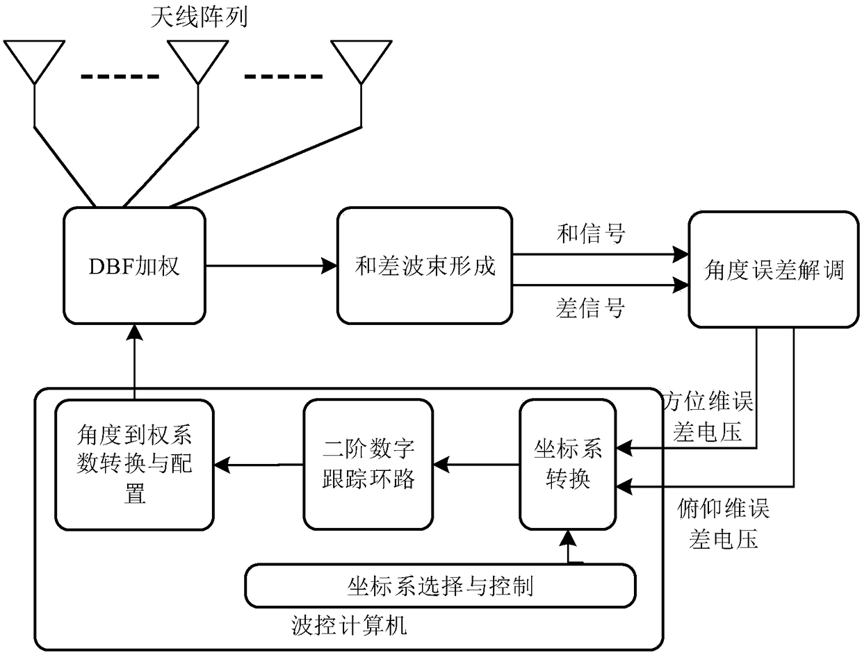
[0017] refer to figure 1 . According to the present invention, the radio frequency signal received by the front is beam-synthesized by the DBF weighting module; then the sum-and-difference beam-forming module generates the combined beam signal, the azimuth difference signal, and the elevation difference signal according to the mutual sum and difference of the azimuth and elevation directions , form the sum / difference beam signal; the difference beamforming module sends the sum / difference beam signal to the back-end angle error demodulation module for processing and then solves the azimuth error voltage and pitch error voltage; finally sends the azimuth error voltage and pitch error voltage to the wave control Computer processing: First, in order to ensure stable tracking of high-elevation-angle targets, it is necessary to use the coordinate system conversion module to convert the coordinates of the spherical array antenna; The second-order digital tracking loop will track the...


PUM


Abstract

The invention provides a self tracking method for a spacecraft dynamic target by a spherical phased array antenna, which aims at providing a simple and reliable tracking method with little hardware resource consumption. The technical scheme comprises steps: radio frequency signals received by four array antenna links form beam forming signals through a DBF weighting module, a difference beam forming module transmits sum/difference beam signals to a rear-end baseband angle error demodulation module for being processed, azimuth error voltage and pitching error voltage are solved, the azimuth error voltage and the pitching error voltage are transmitted to a waveform control computer for being processed, the waveform control computer uses waveform control software to estimate a target incomingwave direction, a two-order digital tracking loop is used to enable a tracking intermediate variable V(Z) and a multi-beam lectronic scanning gain coefficient K0 to be multiplied, a new beam direction theta(Z) is obtained, and finally, the beam direction is updated through the waveform control software of the waveform control computer, after deviation is corrected, the real-time target position is transmitted to a beam forming unit, and self tracking on the dynamic target is completed.

Description

technical field [0001] The invention relates to a method for self-tracking a dynamic target of a spacecraft by a spherical phased array antenna adopting digital beam formation of a measurement and control system in the field of aerospace measurement and control. Background technique [0002] In the multi-beam measurement and control system, the beam control system scans each feed source of the antenna array by scanning method, finds the maximum value of the signal, obtains the deviation according to the position of the maximum value, and then guides the antenna control system to align with the target main beam . This working system leads to three shortcomings in the guiding data. The first is the step jump of the guiding data. Since the beam control system finds the position of the feed source that receives the strongest signal, it is limited by the width of the feed source itself and the installation between the feed sources. Due to the influence of the gap, there must be ...

Claims


Application Information

Patent Timeline
IPC IPC(8): G01S13/72
CPCG01S13/72
Inventor 王文政杜丹俄广西
Owner 10TH RES INST OF CETC
Why Eureka
Try Eureka