Turbine casing runner detection system and method

A technology for detection systems and turbine shells, applied to measuring devices, instruments, etc., can solve the problems of blind spots, high cost, and large labor consumption

Active Publication Date: 2021-03-02
CRRC CHANGZHOU AUTO PARTS CO LTD +1
View PDF10 Cites 0 Cited by
  • Summary
  • Abstract
  • Description
  • Claims
  • Application Information

AI Technical Summary

Problems solved by technology

[0002] In recent years, with the rapid development and technological update of turbochargers, they are widely used in automobiles, aviation, ships and other fields, and the requirements for the main component of the turbine shell are getting higher and higher. Produce meaty, iron filing residues, especially inside part runners, such as figure 1 As shown, since this position is the main functional part of the part, if foreign matter remains, it will seriously affect the performance of the turbocharger. The usual detection process is carried out manually, which consumes a lot of labor, low speed, high cost, and there are visual blind spots , cannot fully identify bad

Method used


Image

  • Turbine casing runner detection system and method
  • Turbine casing runner detection system and method
  • Turbine casing runner detection system and method

Examples


no. 1 example

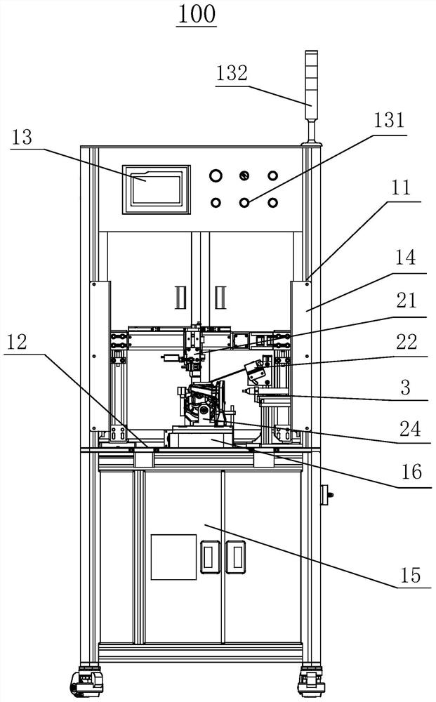
[0038] Please refer to figure 1 , the present embodiment provides a turbine shell runner detection system 100, including a workbench, a functional mechanism, a marking mechanism 3 and a control system.

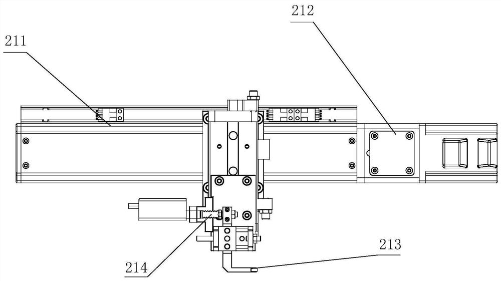
[0039] In this embodiment, the workbench provides a platform for supporting the workpiece, and the functional mechanism is installed on the workbench. The functional mechanism includes a mechanical roller detection device 21, a laser displacement detection device 22, an elastic detection device 23 and a rotary positioning device 24. The positioning device 24 can realize the positioning and rotating operation of the workpiece. The mechanical roller detection device 21, the laser displacement detection device 22 and the elastic detection device 23 detect the workpiece step by step, improve the mechanization of workpiece detection, improve the detection accuracy and detection efficiency; through the marking mechanism 3. Realize the distinction between qualified and unqualified wo...

no. 2 example

[0062] This embodiment provides a method for detecting a flow path of a turbine casing, using the detection system 100 for a flow path of a turbine casing provided in the first embodiment, including the following steps:

[0063] Step S1: Place the workpiece on the workbench, clamp and position the workpiece through the rotary positioning device 24, rotate the workpiece for one circle, and at the same time as the workpiece rotates, the laser displacement detection device 22 uses the laser beam to feed back the distance parameter H1 from the inner surface of the workpiece to the receiver to the external controller, and compared with the first preset value Y1, if H1 does not fall within the range of Y1, the workpiece is unqualified;

[0064] Step S2: Rotate the workpiece to the initial position, the mechanical roller detection device 21 moves to the designated position and contacts the surface of the workpiece, rotates the workpiece to the 270° position, the roller probe of the me...


PUM


Abstract

The invention relates to a turbine casing flow channel detection system and method, belonging to the technical field of surface detection. The turbine shell runner detection system includes a working bench, a functional mechanism, a marking mechanism and a control system. The functional structure is installed on the workbench. The functional mechanism includes a mechanical roller detection device, a laser displacement detection device, an elastic detection device and a rotary positioning device. The marking mechanism is connected to the workbench and the marking mechanism can be close to or far away from the workpiece relative to the workbench. The marking mechanism is used to mark workpieces. The control system is electrically connected with the functional mechanism and the marking mechanism. The turbine shell runner detection system can ensure the effective detection of the blind area of ​​the workpiece, improve the detection accuracy, and is easy and reliable to operate, ensuring the detection effectiveness. The method for detecting the flow channel of the turbine shell, applying the above-mentioned detection system for the flow channel of the turbine shell, can realize the mechanized detection of the flow channel of the turbine shell, reduce labor consumption, and improve detection efficiency.

Description

technical field [0001] The invention relates to the technical field of surface detection, in particular to a turbine shell flow path detection system and method. Background technique [0002] In recent years, with the rapid development and technological update of turbochargers, they are widely used in automobiles, aviation, ships and other fields, and the requirements for the main component of the turbine shell are getting higher and higher. Produce meaty, iron filing residues, especially inside part runners, such as figure 1 As shown, since this position is the main functional part of the part, if foreign matter remains, it will seriously affect the performance of the turbocharger. The usual detection process is carried out manually, which consumes a lot of labor, low speed, high cost, and there are visual blind spots , can not fully identify bad. Therefore, it is urgent to develop new intelligent technology to detect this part. Contents of the invention [0003] The p...

Claims


Application Information

Patent Timeline
Patent Type & Authority Patents(China)
IPC IPC(8): G01D21/02
CPCG01D21/02
Inventor 孙力学孙亚栋胡可清谷春春
Owner CRRC CHANGZHOU AUTO PARTS CO LTD
Why Eureka
Try Eureka