
Novel in-line pump dedicated motor

A technology for special motors and pipeline pumps, applied in electromechanical devices, electrical components, electric components, etc., can solve problems such as the weight of the rotor should not be too large, the heat dissipation effect of the bearing pad is poor, and the oil film cannot be formed, so as to achieve improved operation stability and noise reduction Effect improvement, heat reduction effect

Pending Publication Date: 2018-05-25
WOLONG ELECTRIC GRP CO LTD +1
View PDF0 Cites 10 Cited by
  • Summary
  • Abstract
  • Description
  • Claims
  • Application Information

AI Technical Summary

Problems solved by technology

However, bearing bush temperature control is a difficult problem. Pipeline motors are generally 2P self-lubricating, and the realization of self-lubricating requires the formation of an oil film. There are special requirements for the thickness of the oil film and the viscosity of the oil. Therefore, the weight of the rotor must not be too large. Large, if the weight of the rotor is too heavy, the oil film will not be formed, and the self-lubrication will not be realized; and the self-lubricating method, the temperature of the bearing pad is likely to be high, simply rely on the oil inside the existing bearing seat for lubrication, and there is no heat exchange with temperature difference. The heat dissipation effect of the bearing pad is poor, so it is necessary to improve the self-lubricating method of the bearing to cool down the bearing pad

Method used


Image

  • Novel in-line pump dedicated motor
  • Novel in-line pump dedicated motor
  • Novel in-line pump dedicated motor

Examples


Embodiment Construction

[0030] The implementation of the present invention will be illustrated by specific specific examples below, and those skilled in the art can easily understand other advantages and effects of the present invention from the contents disclosed in this specification.

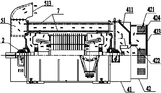
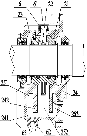
[0031] The invention provides a new type of special motor for pipeline pumps, such as Figure 1 to Figure 6 shown. The special motor for the new pipeline pump includes a machine base 1, an inner fan 5, a stator 11 installed in the machine base 1, and a rotor 12 installed in clearance with the stator 11. The rotor 12 is fixedly installed on the rotating shaft 13, and the outer circumference of the stator iron core is on the The machine base is fixed with a plurality of cooling pipes 7 arranged axially through, and the cooling pipes 7 communicate with the air outlet cover 51 arranged at the shaft extension end; the front and rear ends of the machine base 1 are respectively provided with end covers , a bearing device ...


PUM


Abstract

The invention discloses a novel in-line pump dedicated motor, and the motor comprises a motor base and internal fans. The periphery of a stator iron core is fixedly provided with a plurality of axialthrough cooling tubes on the motor base, and the cooling tubes are communicated with an air outgoing cover disposed at a shaft-extension end of a rotating shaft. A bearing device is installed in a bearing seat, and comprises a bearing bush and an oil slinger, wherein the bearing bush is disposed in the bearing seat. The bearing seat consists of a bearing upper seat and a bearing lower seat. The internal fans are symmetrically disposed on the rotating shaft between the bearing device and a rotor in a fixed manner. The bearing lower seat comprises separator plates which are fixed at left and right sides of the bearing seat body. The separator plates enable the cavity of the bearing seat to be divided into a left oil pool, a central oil pool and a right oil pool, wherein the left, central andright oil pools are communicated. The oil slinger sleeves the periphery of the bearing bush, and is located in the central oil pool of the cavity of the bearing seat. A non-shaft-extension end is provided with an external fan, and is provided with a curved-path fan cover. The motor provided by the invention improves the structure of the bearing seat, improves the self-lubricating effect of a bearing, is additionally provided with the curved-path fan cover, prolongs the propagation path of air, and reduces the noise.

Description

technical field [0001] The invention belongs to the technical field of motors for pipeline pumps on oil transmission lines, and in particular relates to a new type of special motor for pipeline pumps. Background technique [0002] With the development of the national economy, the protection of energy, ecology and the environment has gradually attracted the attention of the international community. Among them, the noise problem has attracted more and more attention. The noise level has become an important indicator to measure the quality of the motor. An important factor in assessing the competitiveness of its products. The special motors for pipeline pumps on oil transmission lines are basically monopolized by foreign countries. Although they can be produced in China now, the noise of the motors is too high and the temperature of the bearing bushes is too high to meet the needs of users. In addition, pipeline pump equipment (localization is a concern of the National Energy A...

Claims


Application Information

Patent Timeline
Patent Type & Authority Applications(China)
IPC IPC(8): H02K5/20H02K9/06H02K5/24H02K5/16H02K1/32H02K1/20H02K7/04
CPCH02K1/20H02K1/32H02K5/16H02K5/20H02K5/24H02K7/04H02K9/06
Inventor 于树坤余志鹏焦华勇王鑫成李学武赵东娜金红
Owner WOLONG ELECTRIC GRP CO LTD
Learn More