OTDR (optical time-domain reflectometry) device based on optical signal monitoring of multi-optical fiber

A multi-channel optical fiber, optical signal technology, applied in measurement devices, transmission monitoring/testing/fault measurement systems, measurement of heat and other directions, can solve the problems of affecting the detection results, low gain, fast measurement time, etc., to achieve accurate measurement results, The effect of high work efficiency and fast monitoring speed

Pending Publication Date: 2018-05-25
国网湖北省电力有限公司信息通信公司
View PDF0 Cites 4 Cited by
  • Summary
  • Abstract
  • Description
  • Claims
  • Application Information

AI Technical Summary

Problems solved by technology

[0004] Among them, the avalanche photodiode of the single photon detection OTDR works in the gated Geiger mode, while the avalanche photodiode of the ordinary OTDR works in the linear mode; the avalanche photodiode working in the linear mode can work in the continuous signal without considering the post-pulse effect In the acquisition state, it has the advantage of fast measurement time, but due to the low gain of the avalanche photodiode working in the linear mode, it cannot detect weak and small optical signals, so the measurement accuracy and measurement distance of ordinary OTDR are limited
[0005] Although single-photon detection OTDR can detect extremely weak optical signals smaller than thermal noise, it can obtain higher measurement accuracy, longer measurement distance and larger dynamic range than ordinary OTDR, which can make up for the shortcomings of ordinary OTDR. However, because the avalanche photodiode of the single-photon detection OTDR works in the gated Geiger mode, it has a certain dead time due to the influence of the after-pulse, resultin

Method used


Image

  • OTDR (optical time-domain reflectometry) device based on optical signal monitoring of multi-optical fiber
  • OTDR (optical time-domain reflectometry) device based on optical signal monitoring of multi-optical fiber
  • OTDR (optical time-domain reflectometry) device based on optical signal monitoring of multi-optical fiber

Examples


Embodiment Construction

[0026] In order to make the technical means, creative features, goals and effects achieved by the present invention easy to understand, the following will further explain how the present invention is implemented in conjunction with the accompanying drawings and specific embodiments.

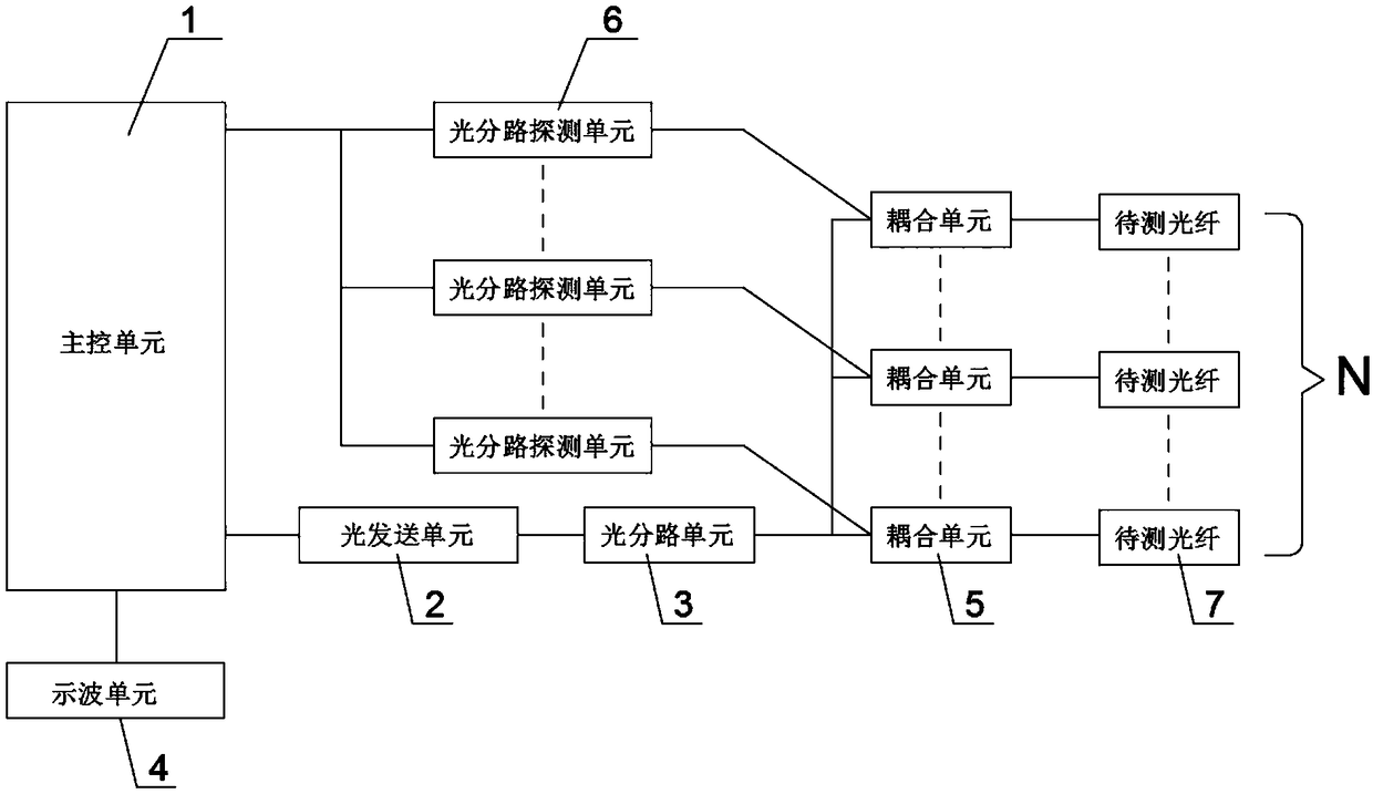
[0027] Such as figure 1 As shown, an OTDR device based on multi-channel optical fiber optical signal monitoring provided by the present invention includes a main control unit 1, an optical transmission unit 2, an optical branching unit 3, an oscilloscope unit 4, N coupling units 5 and N The optical branching detection unit 6; the main control unit 1 is respectively connected with an optical sending unit 2 and the oscilloscope unit 4; the optical sending unit 2 is connected with the optical branching unit 3, and the optical branching unit 3 is correspondingly connected with N coupling units 5 , the input end of each coupling unit 5 is correspondingly connected with an output end of the optical bra...


PUM


Abstract

The invention discloses an OTDR (optical time-domain reflectometry) device based on optical signal monitoring of multi-optical fiber. The OTDR device comprises a master control unit, an optical sending unit, an optical splitting unit, an oscillograph unit, N coupling unit and N optical splitting detection units, wherein the master control unit is respectively connected with the optical sending unit and the oscillograph unit; the optical sending unit is connected with the optical splitting unit; the optical splitting unit is correspondingly connected with N coupling units, the input end of eachcoupling unit is respectively and correspondingly connected with the optical splitting unit and one optical splitting detection unit, the output end of each coupling unit is correspondingly connectedwith a to-be-tested optical fiber; each optical splitting detection unit is correspondingly connected with the master control unit. The OTDR device disclosed by the invention has the advantages thatthe monitoring and the positioning searching on fault points of multiple to-be-tested optical fibers can be performed at the same time, the testing speed is fast, and the measurement precision is high.

Description

technical field [0001] The invention relates to the field of optical time domain reflection, in particular to an OTDR device based on multi-channel optical fiber optical signal monitoring. Background technique [0002] Optical Time-Domain Reflectometry (OTDR) is a precision optoelectronic integrated instrument made by using Rayleigh scattering and backscattering produced by Fresnel reflection when light is transmitted in an optical fiber. Widely used in the maintenance and construction of optical cable lines, it can measure the length of optical fiber, transmission attenuation of optical fiber, joint attenuation and fault location. [0003] At present, there are two main types of OTDR used for optical fiber fault location monitoring: single-photon detection OTDR for single-photon level weak light detection and ordinary OTDR for non-single-photon level light detection; avalanche photodiode (APD) ) as a common photosensitive detection element in the field of laser communicati...

Claims


Application Information

Patent Timeline
IPC IPC(8): H04B10/071H04B10/508G01K13/00H04B10/07G01K11/32
CPCH04B10/07H04B10/071H04B10/508G01K13/00
Inventor 赵锦辉张成吴峥毛竹
Owner 国网湖北省电力有限公司信息通信公司
Why Eureka
Try Eureka