Supercharge Your Innovation With Domain-Expert AI Agents!

Active positioning mechanism for position changing machine

A positioning mechanism and positioner technology, applied in auxiliary devices, auxiliary welding equipment, welding/cutting auxiliary equipment, etc., can solve the problem of inability to achieve pneumatic chuck rotation, achieve simple structure, long service life, and improve work efficiency Effect

Inactive Publication Date: 2018-05-29
JIANGSU DADE HEAVY IND
View PDF9 Cites 1 Cited by
  • Summary
  • Abstract
  • Description
  • Claims
  • Application Information

AI Technical Summary

Problems solved by technology

In the prior art, due to the influence of the pneumatic pipeline, the common pneumatic chuck can only be fixedly installed, which cannot meet the requirements of both the rotation of the pneumatic chuck and the air circuit setting of the pneumatic chuck.

Method used


Image

  • Active positioning mechanism for position changing machine
  • Active positioning mechanism for position changing machine
  • Active positioning mechanism for position changing machine

Examples


Embodiment Construction

[0016] Below the present invention will be further described in conjunction with the embodiment in the accompanying drawing:

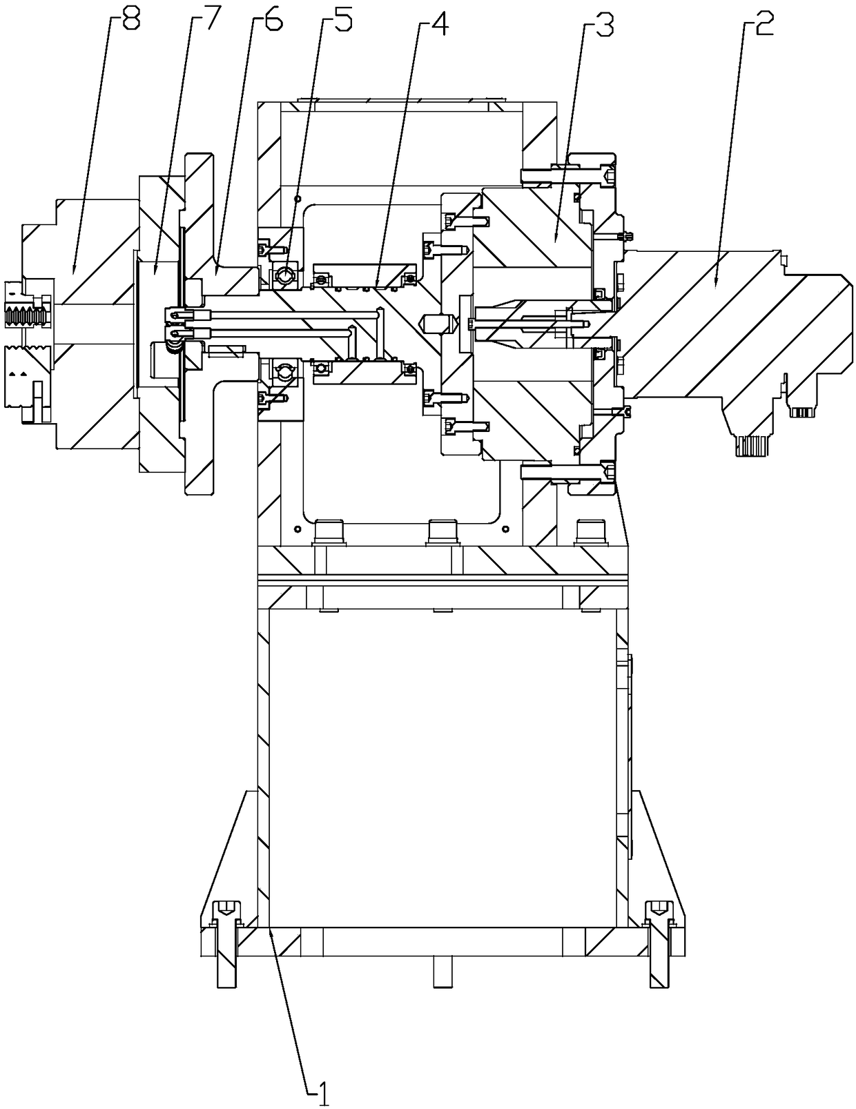
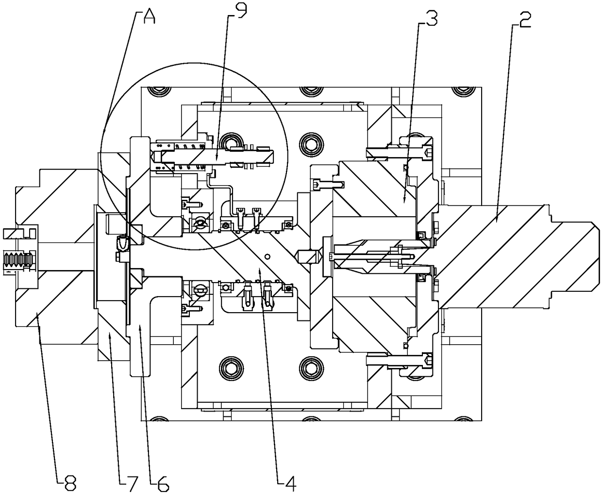
[0017] Such as Figure 1~2 As shown, the present invention mainly includes a main frame 1, a servo motor 2, a reducer 3, a two-way rotating mechanism 4, a turntable 6, a transition disk 7, a pneumatic chuck 8 and a conductive mechanism 9.

[0018] One side of the main frame 1 fixes the servo motor 2, the output end of the servo motor 2 is connected to the reducer 3, the output end of the reducer 3 is connected to the two-way rotating mechanism 4, and the two-way rotating mechanism 4 is connected in the main frame 1 through the bearing 5.

[0019] The front end of the two-way rotating mechanism 4 protrudes from the main frame 1 and is connected to the turntable 6 , the front end of the turntable 6 is connected to the transition disc 7 , and the front end of the transition disc 7 is connected to the pneumatic chuck 8 .

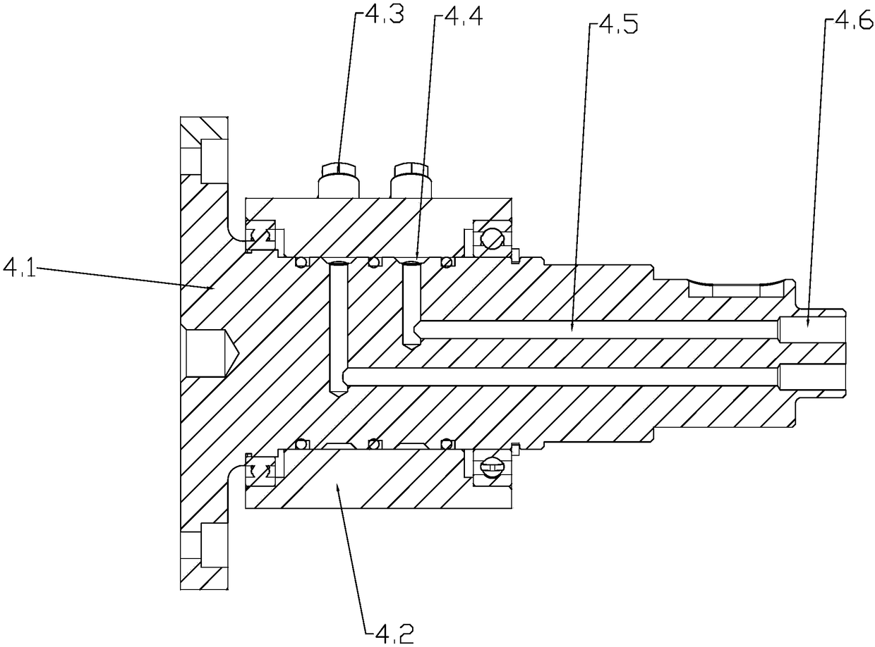
[0020] Such as image 3 As show...


PUM


Abstract

The invention relates to a position changing machine positioning mechanism, in particular to an active positioning mechanism for a position changing machine and belongs to the technical field of position changing machine structures. The active positioning mechanism comprises a main rack, a servo motor, a speed reducer, a two-way rotating mechanism, a rotating disc, a transitional disc, a pneumaticchuck and a conducting mechanism. The servo motor is fixed to one side of the main rack. The output end of the servo motor is connected with the speed reducer. The output end of the speed reducer isconnected with the two-way rotating mechanism. The two-way rotating mechanism is connected into the main rack through a bearing. The front end of the two-way rotating mechanism extends out of the mainrack and is connected with the rotating disc. The front end of the rotating disc is connected with the transitional disc. The front end of the transitional disc is connected with the pneumatic chuck.The main rack is internally provided with the conducting mechanism. The front end of the conducting mechanism is in contact with the rotating disc. By means of the active positioning mechanism, the gas introduction requirement of the pneumatic chuck can be met, and rotation of the pneumatic chuck can be achieved; work efficiency of carbon steel welding is improved; good bonding of workpieces on awelding machine can be maintained all the time; and the active positioning mechanism is long in service life and stable and reliable in work.

Description

technical field [0001] The invention relates to a positioning mechanism of a positioner, in particular to an active positioning mechanism of a positioner, and belongs to the technical field of positioner structures. Background technique [0002] Welding head and tail positioner is a process equipment that drives the workpiece to rotate through the rotation of the worktable on the headstock part and tailstock part to realize the circular seam welding of the workpiece. It is widely used in mechanical equipment, pressure vessels, construction machinery and other industries. [0003] When welding carbon steel, a positioner is required for welding. When the welding is in progress, the two ends of the carbon steel are clamped by the pneumatic chuck of the positioner. Due to the need for carbon steel welding, a pneumatic chuck is required to drive the carbon steel to rotate. In the prior art, the common pneumatic chuck can only be fixedly installed due to the influence of the pne...

Claims


Application Information

Patent Timeline
IPC IPC(8): B23K37/047
CPCB23K37/047
Inventor 夏小帅李明杰宋辉
Owner JIANGSU DADE HEAVY IND
Features
  • R&D
  • Intellectual Property
  • Life Sciences
  • Materials
  • Tech Scout
  • Unparalleled Data Quality
  • Higher Quality Content
  • 60% Fewer Hallucinations
Learn More