
Treatment method for phenolic ammonia wastewater produced by coal pyrolysis

A wastewater treatment and coal pyrolysis technology, which is applied in biological water/sewage treatment, heating water/sewage treatment, degassed water/sewage treatment, etc., can solve the problem of high cost of extraction and dephenolization, achieve cost reduction, increase biochemical sexual effect

Inactive Publication Date: 2018-05-29
HENAN DRAGON INTO COAL TECH CO LTD
View PDF8 Cites 1 Cited by
  • Summary
  • Abstract
  • Description
  • Claims
  • Application Information

AI Technical Summary

Problems solved by technology

[0006] In view of this, the purpose of the present invention is to address the deficiencies in the prior art and provide a method for using phenolic ammonia wastewater as cooling water, so that the temperature of the phenolic ammonia wastewater is between 25 and 40°C during the cooling cycle, which is beneficial to The acidification and hydrolysis of organic matter not only solves the problem of high cost of extraction and dephenolization, but also achieves the effect of biochemical pretreatment of wastewater in advance

Method used


Image

  • Treatment method for phenolic ammonia wastewater produced by coal pyrolysis
  • Treatment method for phenolic ammonia wastewater produced by coal pyrolysis

Examples


Embodiment 1

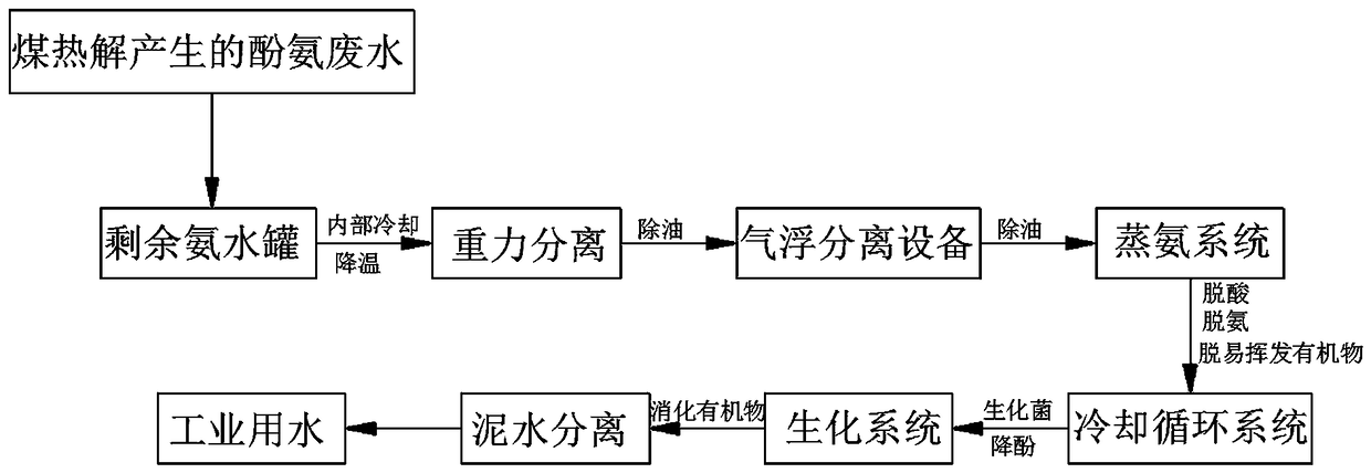
[0025] see figure 1 , the phenolic ammonia wastewater produced by coal pyrolysis overflows from the ammonia water tank to the remaining ammonia water tank, and a cooling device is installed in the remaining ammonia water tank to cool the remaining ammonia water through internal cooling, and the temperature of the remaining ammonia water drops from about 80°C to below 40°C , the solubility of phenolic substances in water decreased significantly, and the solubility of some heavy oils and light oils in phenolic ammonia wastewater decreased in water. Among them, most of them were phenolic oils. These oils were separated from phenolic ammonia wastewater and separated by gravity. The oil is separated to complete the primary pretreatment of phenolic ammonia wastewater; the phenolic ammonia wastewater pretreated by cooling and degreasing is passed through the air flotation pretreatment equipment, so that small oil droplets float up under the drive of air bubbles, gather on the liquid s...

Embodiment 2

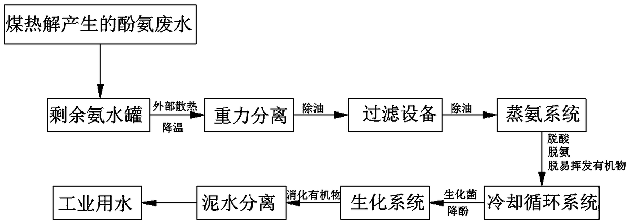
[0027] see figure 2 , the phenolic ammonia wastewater overflows from the ammonia water tank to the remaining ammonia water tank, the remaining ammonia water tank is set appropriately larger, and the heat sink is installed outside the tank body, so that the remaining ammonia water can be cooled naturally through external heat dissipation, and the temperature of the ammonia water drops from about 80°C to below 50°C , the solubility of phenolic substances in water decreased significantly, and the solubility of some heavy oils and light oils in phenolic ammonia wastewater decreased in water. Among them, most of them were phenolic oils. These oils were separated from phenolic ammonia wastewater and separated by gravity. The oil is separated out to complete the primary pretreatment of phenolic ammonia wastewater; the phenolic ammonia wastewater pretreated by cooling and degreasing passes through the hydrophilic and oleophobic filter equipment, and small oil droplets gather on the su...


PUM


Abstract

The invention discloses a treatment method for phenolic ammonia wastewater produced by coal pyrolysis and belongs to the technical field of wastewater treatment. The treatment method specifically comprises the following steps: 1, carrying out cooling and oil-removing pre-treatment; 2, carrying out air flotation or filtering and oil-removing pre-treatment; 3, carrying out ammonia evaporation pre-treatment; 4, carrying out turbid water cooling and circulating biological pre-treatment; 5, carrying biochemical treatment and deep treatment. By adopting the treatment of the method, an extraction andphenol removing procedure in an ammonia evaporation and phenol removing process is omitted; the sewage treatment cost of a coal chemical industry is reduced, and zero emission of the wastewater stillcan be realized; the treatment method disclosed by the invention, has very important meanings in the aspects of environmental protection and energy saving or economy.

Description

technical field [0001] The invention relates to the technical field of wastewater treatment, in particular to a method for treating phenol ammonia wastewater produced by coal pyrolysis. Background technique [0002] Coal itself contains moisture. When coal is heated and pyrolyzed, it will produce wastewater containing ammonia and phenol, commonly known as phenolic ammonia wastewater. Phenolic ammonia wastewater participates in the circulation and cooling of coal pyrolysis gas. The excess must be discharged from this system. The discharged phenolic ammonia wastewater It is usually called residual ammonia water, also known as phenolic ammonia wastewater, but it is customary to call the phenolic ammonia wastewater discharged into the residual ammonia tank as residual ammonia water, and after it comes out of the residual ammonia tank, it is called phenolic ammonia wastewater or directly called ammonia water. [0003] Sewage treatment in the coal chemical industry is recognized a...

Claims


Application Information

Patent Timeline
IPC IPC(8): C02F9/14C02F101/16C02F101/34
CPCC02F1/001C02F1/04C02F1/20C02F1/24C02F1/40C02F3/30C02F3/34C02F9/00C02F2101/16C02F2101/345
Inventor 朱书成王希彬王洪博汪国敏王晓丽
Owner HENAN DRAGON INTO COAL TECH CO LTD
Features
  • Generate Ideas
  • Intellectual Property
  • Life Sciences
  • Materials
  • Tech Scout
  • Unparalleled Data Quality
  • Higher Quality Content
  • 60% Fewer Hallucinations
Learn More