
Industrial energy-saving boiler system

An industrial boiler technology, applied in steam boilers, steam boiler accessories, steam boiler components, etc., can solve the problems of wasting water resources, high labor intensity of workers, and long heating time, so as to improve the utilization rate of heat, Effect of shortening heating time and saving fuel energy

Inactive Publication Date: 2018-05-29
天津市新聚祥科技开发有限公司
View PDF0 Cites 2 Cited by
  • Summary
  • Abstract
  • Description
  • Claims
  • Application Information

AI Technical Summary

Problems solved by technology

[0003] 1. The boiler consists of two parts: the pot and the furnace. Most of the commonly used pots and furnaces are cylindrical or square. This structure makes the boiler burn a large amount of fuel during the heating process to meet the demand for steam or high-temperature water. At the same time, the boiler The water inside is heated slowly and unevenly during the heating process, resulting in long heating time
[0004] 2. The boiler fuel is mainly coal. The structure of the furnace cavity and the oxygen content affect the combustion efficiency and combustion stability of coal and other fuels, thus restricting the heating time of the boiler and making the boiler heating process consume a lot of energy
[0005] 3. The traditional slag discharge method usually uses a small cart to directly transport the hot slag to the slag yard, and then cools it with cold water before transporting it out, which makes the labor intensity of the workers high, the risk is high, and a large amount of water resources needs to be wasted, and at the same time When the hot slag is cooled by cold water, a large amount of hot air and dust will be generated, which not only wastes waste heat energy, but also seriously pollutes the environment

Method used


Image

  • Industrial energy-saving boiler system

Examples


Embodiment Construction

[0019] In order to better understand the present invention, the present invention will be further described below in conjunction with specific embodiments and accompanying drawings.

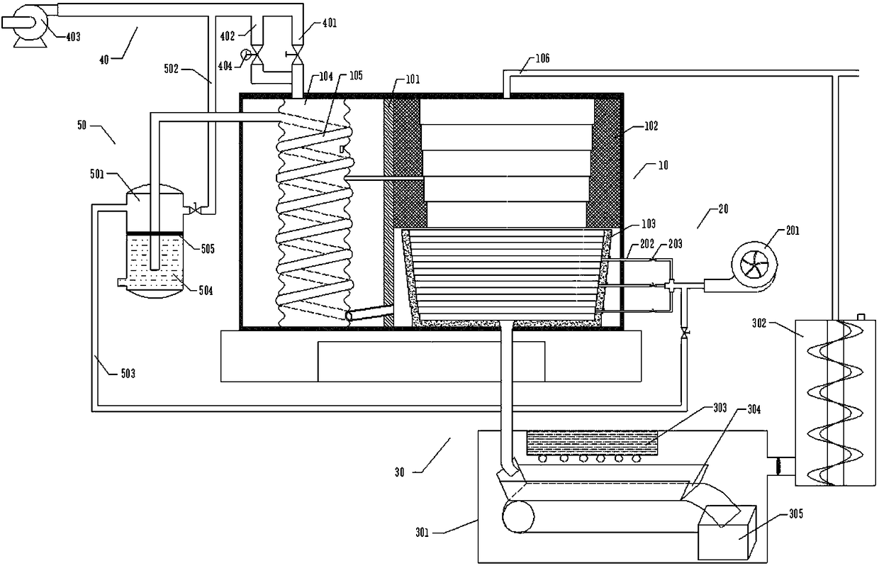
[0020] Such as figure 1 As shown, an industrial energy-saving boiler system includes a boiler main body 10, an air supply part 20, a waste residue treatment part 30, a water supply part 40 and a dust removal part 50; body 103, water storage tank 104 and heat exchange tube 105, the partition plate 101 is set to divide the inner cavity of the boiler body 10 into left and right chambers, the heating pot body 102 and the furnace body 103 are arranged in one room, and the heating pot body 102 Furnace body 103 is arranged below, and water storage tank 104 and heat exchange pipe 105 are arranged in another room; heat, and the side of the heating pot 102 close to the partition 101 is set to communicate with the water storage tank 104 through the water inlet pipe, and the inner side wall of the furnace b...


PUM


Abstract

The invention provides an industrial energy-saving boiler system which comprises a boiler main body, a gas supply portion, a waste slag treating portion, a water supplement portion and a dust removalportion. The boiler main body is mainly composed of a partition plate, a heating boiler body, a hearth portion, a water storage tank and a heat exchange pipe. The partition plate divides an inner cavity of the boiler main body into a left chamber and a right chamber, the heating boiler body and the hearth portion are arranged in one chamber, the water storage tank and the heat exchange pipe are arranged in the other chamber, the inner side wall of the heating boiler body is of a vortex structure, the heating boiler body is arranged to communicate with the water storage tank, the inner side wall of the hearth body is also arranged to be of a vortex structure, the side wall of the hearth body is arranged to be connected with the gas supply portion, a slag outlet formed in the bottom wall ofthe hearth body is arranged to be connected with the waste slag treating portion, the hearth body is arranged to communicate with the front end of the heat exchange pipe, the top of the water storagetank is arranged to communicate with the water supplement portion, and the tail end of the heat exchange pipe is arranged to communicate with the dust removal portion. By the adoption of the system, fuel energy of the boiler can be sufficiently utilized, production efficiency is improved, and it is ensured that the heating process of the boiler body is stable.

Description

technical field [0001] The invention relates to the technical field of boiler equipment, in particular to an industrial energy-saving boiler system. Background technique [0002] The boiler is a kind of energy conversion equipment. The energy input to the boiler includes chemical energy in the fuel, electric energy, etc., and the boiler outputs steam, high-temperature water or organic heat carrier with certain heat energy. The hot water or steam generated in the boiler can directly provide the required heat energy for industrial production and people's life, and can also be converted into mechanical energy through a steam power device, or converted into electrical energy through a generator. With the enhancement of people's awareness of energy saving and environmental protection, the improvement of the boiler system is also continuously developed and perfected. The existing boilers have the following problems in the actual use process: [0003] 1. The boiler consists of two...

Claims


Application Information

Patent Timeline
IPC IPC(8): F22B1/22F22B37/02F22D1/24F23J1/06F23J15/02
CPCF22B1/22F22B37/02F22D1/24F23J1/06F23J15/022
Inventor 陈荣祥
Owner 天津市新聚祥科技开发有限公司
Learn More