Vertical-type electric dryer

A drying machine, vertical technology, applied in the direction of drying machine, drying, drying solid materials, etc., can solve the problems of material pollution, poor discreteness, high viscosity, etc., to reduce production costs, improve discreteness, The effect of low discharge temperature

Inactive Publication Date: 2018-05-29
赵世青
View PDF1 Cites 2 Cited by
  • Summary
  • Abstract
  • Description
  • Claims
  • Application Information

AI Technical Summary

Problems solved by technology

However, it has been found in practice that such vertical dryers generally have the following problems: (1) heating devices such as hot blast stoves are provided, and coal-fired heating is used for heating, resulting in serious pollution; (2) heating devices such as hot blast stoves are installed in vertical dryers At the bottom of the dryer, the temperature of the lower part of the shell (also known as the drying cylinder) is very high, but the temperature of the upper part is difficult to guarantee, especially when the wet material first enters, the wet material that enters initially absorbs a large amount of heat, and the surface is quickly evaporated and dried , a large amount of water vapor is generated. At this time, the material will continue to absorb heat during the falling process. The heat lost in the upper part of the shell cannot be quickly compensated, and the local temperature drops significantly. When the follow-up wet material is continuously fed into the shell, due to the The local temperature is low, and the surface of the wet material can no longer be dried and heated immediately. After the low-temperature wet material is mixed with water vapor, the water vapor in the water vapor recondenses and liquefies to form a slurry with the wet material, which has poor dispersion and high viscosity. It is easy to cause material blockage; (3) Since the heating device is set at the bottom of the shell, the temperature of the material cannot be cooled during the falling process, resulting in a high temperature of the material after drying. On the one hand, it is easy to burn the transportation equipment or burn the operator; On the one hand, a large amount of heat is taken away by the discharge material, the heat loss is serious, and the energy consumption is high; (4) the heating device is arranged at the bottom of the shell, and the heat exchange between the heat source and the material mainly depends on the remote radiation and convection of the heat of the heating device. Low exchange efficiency, low heat utilization efficiency, and high energy consumption; (5) Since coal is used as fuel, some chemical gases and dust are inevitably generated during the combustion process, which is easy to pollute the drying materials, so its applicability restricted

Method used


Image

  • Vertical-type electric dryer
  • Vertical-type electric dryer
  • Vertical-type electric dryer

Examples


Embodiment 1

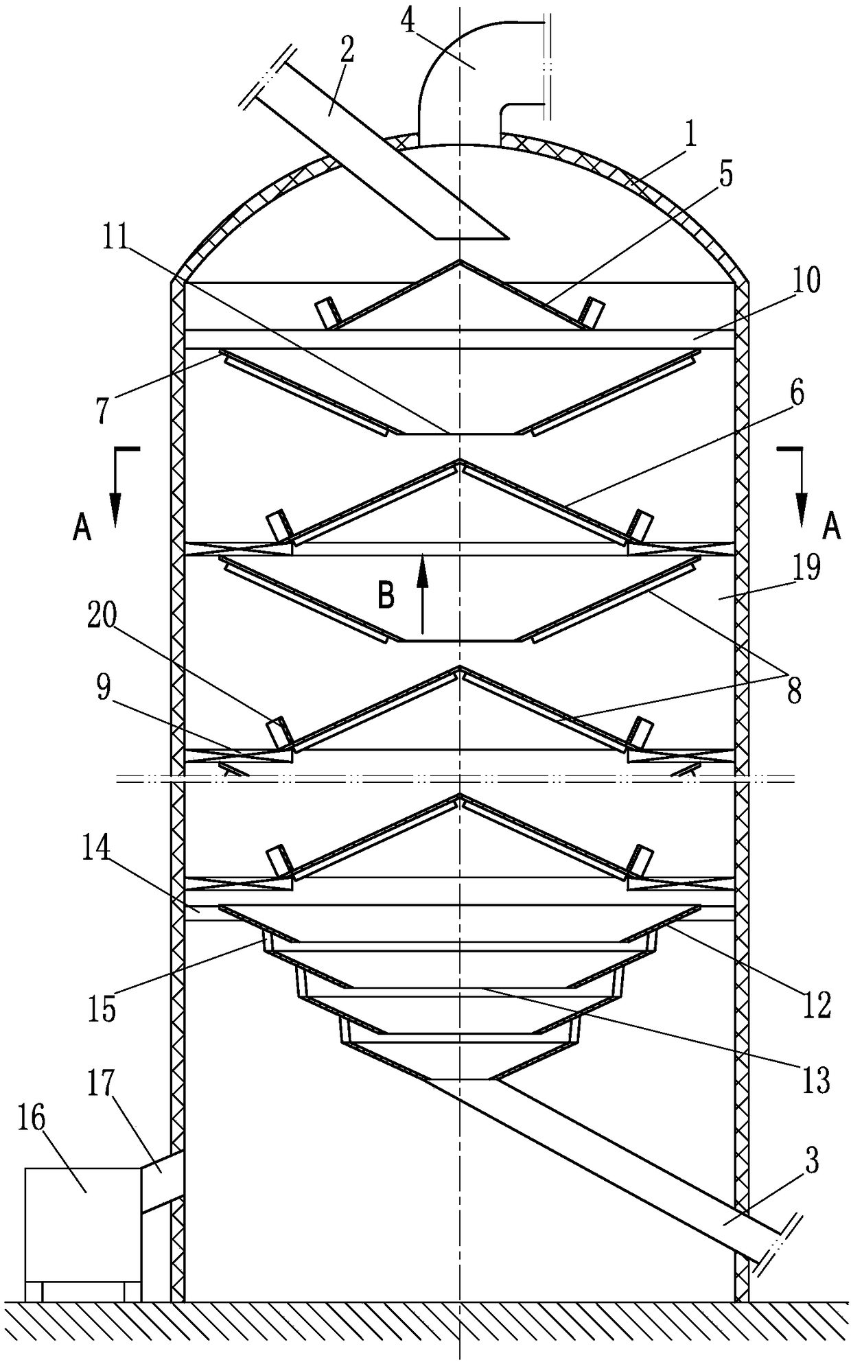
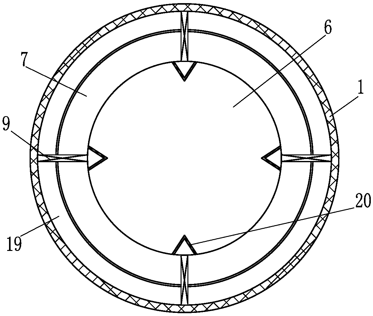
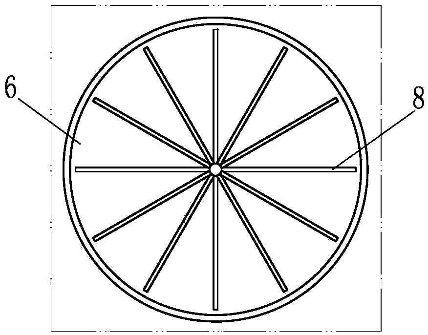
[0033] Such as figure 1 , figure 2 and image 3 The vertical electric dryer shown in the present invention includes a drying cylinder 1, a feed channel 2, a discharge channel 3, an air outlet pipe 4 and a bulk material device 5, and the feed channel 2 and the air outlet pipe 3 are arranged On the top of the drying cylinder 1, the bulk material device 5 is specifically an umbrella-shaped bulk material cone, and the umbrella-shaped bulk material cone is arranged corresponding to the opening that the feed channel 2 communicates with the inside of the drying cylinder 1; in addition, the drying The electric heating cone combination device, the cooling cone combination device and the convection ventilation device are arranged in sequence from top to bottom in the drying cylinder body 1, and the electric heating cone combination device, the cooling cone combination device and the convection ventilation device are respectively connected with the drying cylinder body 1 Connected, wh...

Embodiment 2

[0048] Such as Figure 5 The difference between the vertical electric dryer of the present invention shown in Embodiment 1 is that the forward feeding heating cone 6 is used instead of the umbrella-shaped bulk material cone as a bulk material device. The guide heating cone 7 is fixedly connected with the drying cylinder 1 through the short connecting frame 9; in addition, the lowest end of the electric heating cone assembly is a reverse feed guide heating cone, and the corresponding cooling cone assembly consists of multiple forward blanking The cone 22 and a plurality of reverse blanking cones 12 are formed, and the forward blanking cones 22 are all arranged above the reverse blanking cones 12, and the contour dimensions of the multiple forward blanking cones 22 increase sequentially from top to bottom. Large, the outline size of multiple reverse blanking cones 12 decreases sequentially from top to bottom, and the adjacent forward blanking cones 22 or / and reverse blanking con...

Embodiment 3

[0052] Such as Figure 6 The difference between the shown vertical electric dryer of the present invention and the second embodiment is that in the electric heating cone combination device, the adjacent reverse feeder heating cone 7 and the forward feeder heating cone 6 are connected into one body through a connecting bracket. The connecting bracket includes a short connecting bracket 23 and a long connecting bracket 24 , the forward feeding heating cone 6 at the top and the reverse feeding heating cone 7 at the bottom are respectively fixedly connected to the drying cylinder 1 through the short connecting frame 9 .

[0053] The advantages and application methods of the technical solution described in this example are similar to those in Embodiment 2, and will not be repeated here. It should be pointed out that, in the technical solution described in this example, since the short connecting bracket 23 and the long connecting bracket 24 are used in the electric heating cone com...


PUM


Abstract

The invention discloses a vertical-type electric dryer. The vertical-type electric dryer comprises a drying barrel, a feeding channel, a discharging channel and an air exhausting pipe. The feeding channel and the air exhausting pipe are arranged at the top of the drying barrel. The vertical-type electric dryer is characterized in that an electric heating cone combination device, a cooling cone combination device and a convection ventilating device are further sequentially arranged inside the drying barrel from top to bottom; the electric heating cone combination device, the cooling cone combination device and the convection ventilating device are connected with the drying barrel; gaps are both reserved between the electric heating cone combination device and the drying barrel as well as between the cooling cone combination device and the drying barrel; and the upper area and the lower area, corresponding to the gaps, of the inside of the drying barrel form a convection channel. The vertical-type electric dryer has the remarkable advantages of being high in heat exchange efficiency, small in energy consumption, high in applicability, economical, environmentally friendly and the like. The vertical-type electric dryer can effectively replace various sorts of existing vertical-type dryers and is suitable for drying various block-shaped or granular powdered raw materials like cementraw materials, slag, pulverized fuel ash and coke, and the application prospects are broad.

Description

technical field [0001] The invention relates to a drying equipment for industrial raw materials, in particular to a vertical drying machine suitable for drying lumpy or powdery raw materials such as cement raw materials, slag, fly ash and coke. Background technique [0002] As we all know, in the cement production process, the production raw materials are generally dried and processed so that the water content of the production raw materials meets the requirements of the cement production process technical standards before they can be put into production and use. This is the basic prerequisite for the production of qualified cement products. At present, the mainstream drying equipment used by cement production enterprises is a vertical dryer, a typical example is the vertical dryer disclosed in Chinese Patent No. 03234469.4. However, it has been found in practice that such vertical dryers generally have the following problems: (1) heating devices such as hot blast stoves are...

Claims


Application Information

Patent Timeline
Patent Type & Authority Applications(China)
IPC IPC(8): F26B17/16F26B21/00F26B23/06F26B25/00
CPCF26B17/16F26B21/004F26B23/06F26B25/002F26B2200/08
Inventor 赵子文赵世青
Owner 赵世青
Why Eureka
Try Eureka