
Stator-rotor structure for high-efficiency permanent-magnet hub motor

A technology for in-wheel motors, stators and rotors, which is applied in the shape/style/structure of magnetic circuits, motors, and rotating parts of magnetic circuits, etc., can solve the problems of shortening the service life of in-wheel motors, damage of power batteries and permanent magnets, and air-gap magnetic density waveforms. It can improve the back EMF waveform, reduce the eddy current loss and torque ripple, and reduce the leakage flux.

Inactive Publication Date: 2018-05-29
HARBIN UNIV OF SCI & TECH
View PDF9 Cites 2 Cited by
  • Summary
  • Abstract
  • Description
  • Claims
  • Application Information

AI Technical Summary

Problems solved by technology

In fact, it is often used with a reduction device to meet the requirements of deceleration and torque increase, but the introduction of the reduction device wears quickly, is not easy to maintain, and easily shortens the service life of the hub motor
The maximum speed of the low-speed outer rotor hub motor is 2000r / min, without the need for a deceleration mechanism, and the transmission efficiency is further improved. However, when the car starts and climbs a slope, the demand for motor torque is large, which is likely to cause a large current, which will damage the power battery and permanent magnet. cause damage
[0004] Due to the complex operating conditions of electric vehicles and the need to meet the requirements of fast start, acceleration, climbing and frequent start and stop, the in-wheel motor is required not only to have a high torque density, but also to have a wider speed range and a wider range. Strong overload capacity, if the respective advantages of the inner rotor hub motor and the outer rotor hub motor can be combined and applied to the same motor, it will be of great significance to the development of new energy vehicles. In addition, the traditional permanent magnet synchronous motor, the air gap flux density The sinusoidal nature of the waveform is poor, and the harmonic content of the back electromotive force is large, which easily increases the eddy current loss of the motor, which in turn causes the temperature rise of the motor and seriously affects the efficiency of the motor. This problem also needs to be solved urgently

Method used


Image

  • Stator-rotor structure for high-efficiency permanent-magnet hub motor
  • Stator-rotor structure for high-efficiency permanent-magnet hub motor

Examples


specific Embodiment approach

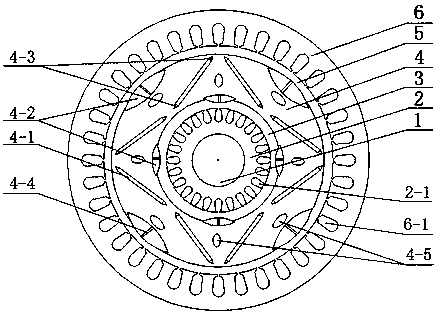
[0015] Such as figure 1 As shown, a high-efficiency permanent magnet hub motor stator-rotor structure includes a rotating shaft 1, an inner stator core 2, an inner air gap 3, a rotor core 4, an outer air gap 5, an outer stator core 6, and an inner stator slot 2-1. Main permanent magnet 4-1, auxiliary permanent magnet 4-2, magnetic isolation block 4-3, magnetic isolation strip 4-4, cooling hole 4-5, outer stator slot 6-1, etc.

[0016] The structure of the present invention is inner stator-rotor-outer stator from inside to outside. Both stator cores have their own windings and can work independently. The same rotor core 4 inner rotor is realized by controlling the on and off of the stator winding current. Freely switch between the drive modes of the outer rotor and the motor, when the motor needs to provide a high-speed, low-torque operating mode, the rotor core 4 and the inner stator core 2 form a high-speed inner rotor hub motor, and the magnetic circuit is a small V structur...


PUM


Abstract

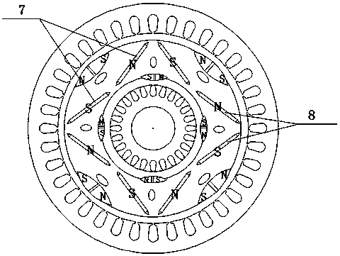
The invention discloses a stator-rotor structure for a high-efficiency permanent-magnet hub motor. The stator-rotor structure comprises a rotating shaft, an inner stator core, an inner airgap, a rotorcore, an outer airgap, an outer stator core, main permanent magnets, auxiliary permanent magnets and the like, wherein the inner stator core sleeves the rotating shaft; the rotor core sleeves the inner stator core; the outer stator core sleeves the rotor core; the main permanent magnets are embedded into the rotor core to form a V-shaped structure; and the auxiliary permanent magnets are embeddedinto the inner surface and the outer surface of the rotor core separately and the shapes are designed into spindle shapes or diamond shapes. The stator-rotor structure has the advantages that the same rotor core can be switched between an inner rotor mode and an outer rotor mode, so that the hub motor has the advantages of high torque of an outer rotor motor and a high speed of an inner rotor motor and is suitable for more working conditions. Relatively large flux area is provided through combination of the main permanent magnets and the auxiliary permanent magnets, the internal space of therotor core is fully utilized and the efficiency and the power factor are improved. Through the arc-shaped surfaces of the spindle-shaped auxiliary permanent magnets, an airgap magnetic field and backelectromotive force waveforms of windings can be obviously improved, the eddy-current loss and the torque ripples are reduced and an airgap flux density waveform is closer to a sine wave; and throughdesign of magnetic isolation strips, magnetic isolation blocks and oval heat emission holes, the leakage flux is effectively reduced. The effective airgap area of the motor is increased through the double airgaps and the torque density of the motor is improved.

Description

technical field [0001] The invention relates to the technical field of hub motors, in particular to a high-efficiency permanent magnet hub motor stator and rotor structure. Background technique [0002] With the increasingly prominent problems of energy shortage and environmental pollution, energy-saving and environment-friendly new energy vehicles have gradually become the development trend of the world's automobile industry. The in-wheel motor drive system is known as the ultimate driving method of electric vehicles because of its simple structure, compact size, and high transmission efficiency. Motors that can be used as in-wheel motors include DC motors, induction motors, permanent magnet synchronous motors, switched reluctance motors, etc. Among them, permanent magnet synchronous motors have the advantages of small size, light weight, fast response, and high efficiency, and become new energy sources. The best choice for car hub motors. [0003] According to the differ...

Claims


Application Information

Patent Timeline
Patent Type & Authority Applications(China)
IPC IPC(8): H02K1/27H02K1/32
CPCH02K1/2766H02K1/32Y02T10/64
Inventor 戈宝军刘卢燕王立坤陶大军刘海涛陈鑫磊毕达窦庆鹏
Owner HARBIN UNIV OF SCI & TECH
Learn More