Voltage polarity switching device and method

A voltage polarity and switching device technology, which is applied in the field of mass spectrometry, can solve the problems of switching speed limit, not fast enough switching time, limited service life, etc., and achieve the effect of speeding up switching, reducing design cost, and reducing arcing

Pending Publication Date: 2018-05-29
FOCUSED PHOTONICS +1
View PDF0 Cites 2 Cited by
  • Summary
  • Abstract
  • Description
  • Claims
  • Application Information

AI Technical Summary

Problems solved by technology

[0003] 1. A high-voltage relay is used for switching, but because the instantaneous high-voltage arc will be generated at the moment of switching the relay, it will cause the aging of the contacts, resulting in a limited service life, and the switching time is

Method used


Image

  • Voltage polarity switching device and method
  • Voltage polarity switching device and method
  • Voltage polarity switching device and method

Examples


Embodiment 1

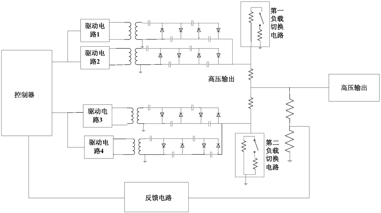
[0037] figure 1 A schematic diagram of the circuit structure of the voltage polarity switching device of this embodiment is given schematically, as shown in figure 1 As shown, the voltage polarity switching device includes:

[0038] a controller, the output end of the controller is connected to a positive pressure output module and a negative pressure output module;

[0039] Positive voltage output module, the positive voltage output module is driven by at least two drive circuits arranged in parallel to couple at least two sets of transformers to output positive voltage. voltage output terminal;

[0040] Negative voltage output module, the negative voltage output module is driven by at least two drive circuits arranged in parallel to couple at least two sets of transformers to output negative voltage. A voltage output terminal; the first load switching circuit is connected to the second load switching circuit;

[0041] Feedback circuit, the input end of the feedback circu...

Embodiment 2

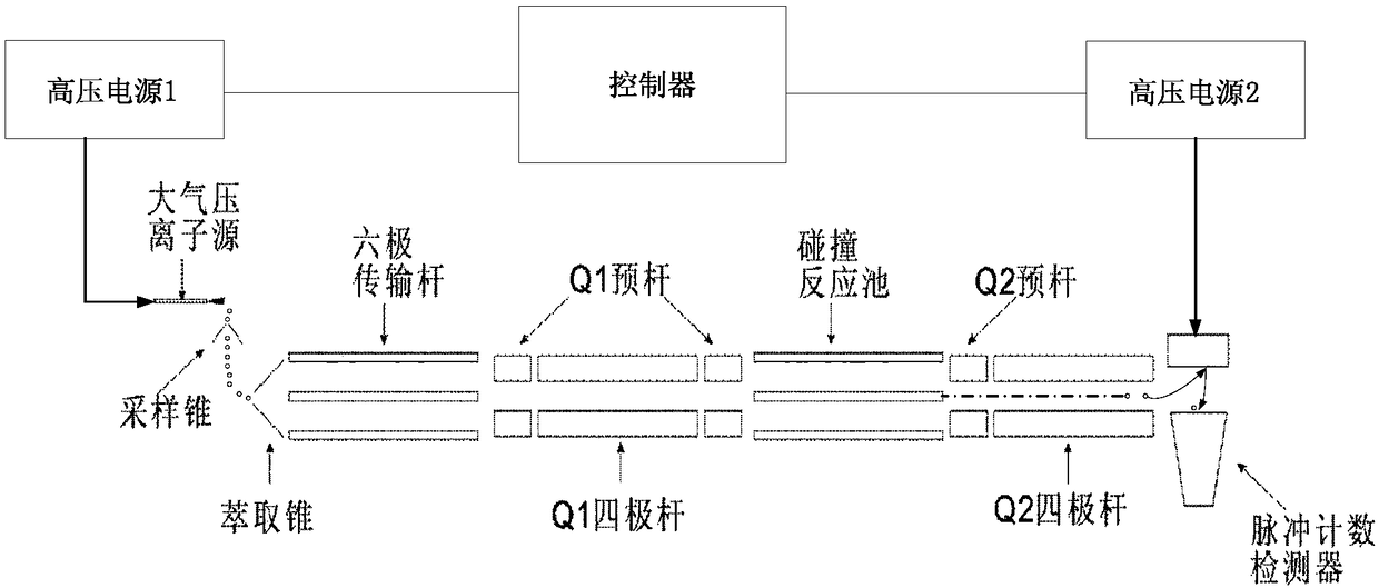
[0054] This embodiment is an application example of the voltage polarity switching device of Embodiment 1 of the present invention on a mass spectrometer.

[0055] In this application example, the mass spectrometer includes an atmospheric pressure ion source, sampling cone, extraction cone, hexapole transfer rod, Q1 pre-rod, Q1 quadrupole, collision reaction cell, Q2 pre-rod, Q2 quadrupole and pulse Counting detector; the mass spectrometer also includes two sets of voltage polarity switching devices, which switch the voltage polarity of the atmospheric pressure ion source and the pulse counting detector respectively, and the controllers of the two sets of voltage polarity switching devices are shared, and the remaining parts are composed of High-voltage power supply 1 and high-voltage power supply 2 in the figure are shown.


PUM


Abstract

The invention relates to a voltage polarity switching device, comprising a controller, the output end of which is connected to a positive pressure output module group and a negative pressure output module group. The voltage polarity switching device also comprises a positive pressure output module group. At least two sets of transformers are driven by at least two drive circuits arranged in parallel, and positive voltage is output in a coupling manner. The output end is divided into two paths, wherein one path is connected to a first load switching circuit, and the other path is connected to the output end of voltage. The voltage polarity switching device also comprises a negative pressure output module group. At least two sets of transformers are driven by at least two drive circuits arranged in parallel, and negative voltage is output in a coupling manner. The output end is divided into two paths, wherein one path is connected to a second load switching circuit, and the other path isconnected to the output end of voltage. The first load switching circuit is connected to the second load switching circuit. The voltage polarity switching device also comprises a feedback circuit, which is used for monitoring the voltage of the output terminal of voltage and is transmitted to the controller. The invention also relates to a voltage polarity switching method. The invention is advantageous in that the switching speed is fast, circuit interference is little, and design cost is low.

Description

technical field [0001] The invention relates to the field of mass spectrometry, in particular to a switching device and method for ion source and detector voltage polarity in tandem mass spectrometry. Background technique [0002] In the tandem mass spectrometry (MS / MS) analysis involving the detection of positive and negative ions, it is necessary to change the voltage polarity of the ion source and detector, and the voltage polarity is required to change very quickly to achieve fast switching of positive and negative ions, but the actual The application is always limited by the switching speed of the voltage polarity. At present, the common voltage polarity switching methods are as follows, but all have defects: [0003] 1. A high-voltage relay is used for switching, but because the instantaneous high-voltage arc will be generated at the moment of switching the relay, it will cause the aging of the contacts, resulting in a limited service life, and the switching time is n...

Claims


Application Information

Patent Timeline
IPC IPC(8): H02M1/10H02M3/00
CPCH02M1/10H02M3/00
Inventor 张建杨继伟钱隆韩双来
Owner FOCUSED PHOTONICS
Why Eureka
Try Eureka