Solar cell capable of improving photoelectric conversion efficiency

A technology of photoelectric conversion efficiency and solar cells, which is applied in the field of solar energy, can solve the problems of reducing photoelectric conversion efficiency, cumbersome series flipping, inconvenient adjustment of solar panels, etc., and achieves the effects of improving photoelectric conversion efficiency, high practical performance, and convenient operation

Pending Publication Date: 2018-05-29
张家港市互惠光电有限公司
View PDF1 Cites 6 Cited by
  • Summary
  • Abstract
  • Description
  • Claims
  • Application Information

AI Technical Summary

Problems solved by technology

[0002] Because of energy and environmental issues, solar cells have attracted public attention. A solar cell is a power generation device that uses the photoelectric effect to obtain photoelectric power. The patent document CN106449777A provides a solar cell module with high photoelectric conversion efficiency. This structure Including solar panels, the first type of solar cell and the second type of solar cell, the first type of solar cell and the second type of solar cell have opposite polarities on the front side of the light-receiving surface. The reduction of photoelectric conversion efficiency and the cumbersome problems of series flipping, and the flexibility to increase the output power, because the sun is constantly rotating, sometimes the sunlight will not be able to directly shine on the solar panel, this structure is not convenient for the solar panel. Adjusting the tilt angle will reduce the conversion efficiency of the solar panel and affect the normal use of the solar panel. Therefore, we propose a solar cell that improves the photoelectric conversion efficiency to solve the above problems

Method used


Image

  • Solar cell capable of improving photoelectric conversion efficiency
  • Solar cell capable of improving photoelectric conversion efficiency
  • Solar cell capable of improving photoelectric conversion efficiency

Examples


Embodiment

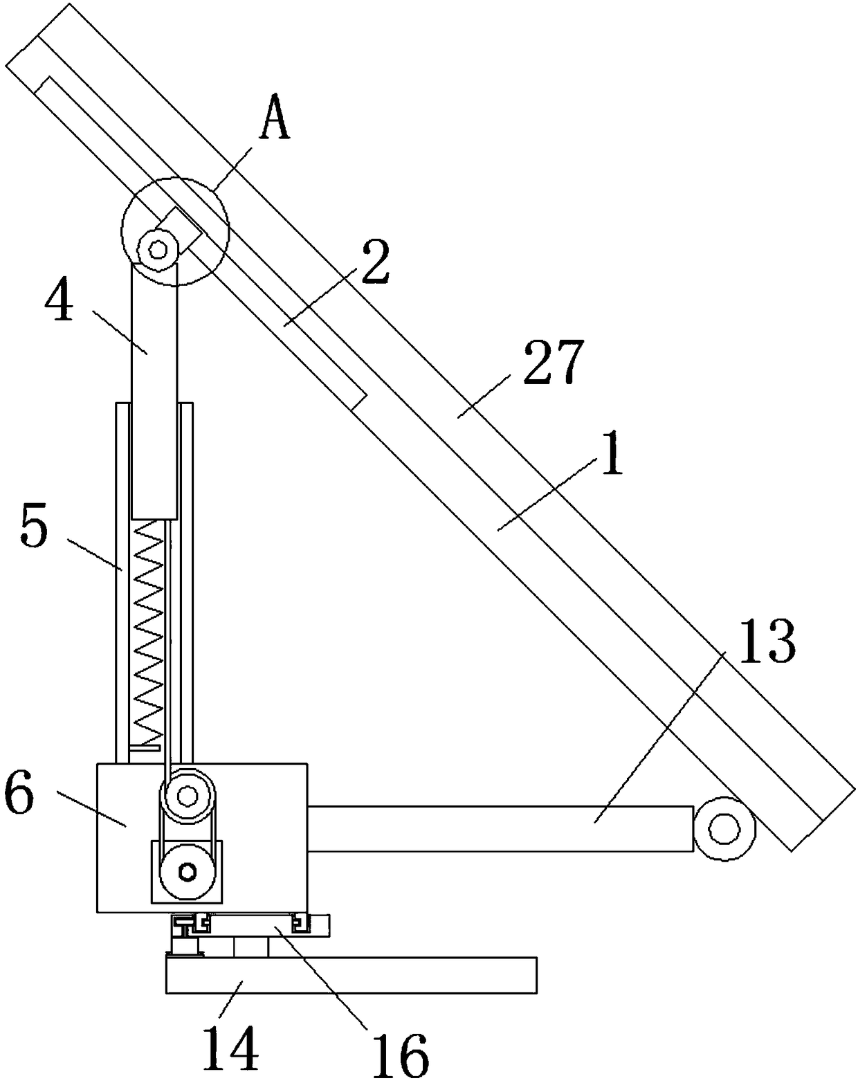
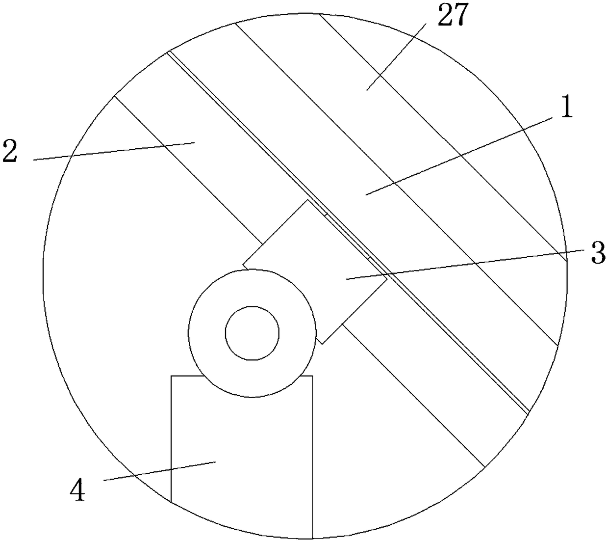
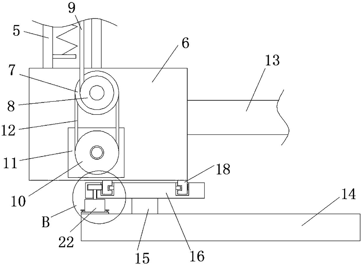
[0024] refer to Figure 1-5 In this embodiment, a solar cell with improved photoelectric conversion efficiency is proposed, including a solar cell 27 fixedly installed on the mounting plate 1, and a chute 2 is provided on the side of the mounting plate 1 away from the cell plate 27, and the chute 2 A traction block 3 is slidably installed, and one side of the traction block 3 extends to the outside of the mounting plate 1 and is hinged with a vertical bar 4. The outer side of the vertical bar 4 is slidably installed with a sleeve 5, and the bottom of the sleeve 5 is welded with a support plate 6. One side of the support plate 6 is rotated with a first sprocket 7, the first sprocket 7 is welded with a reel 8, the bottom of the vertical bar 4 is fixedly connected with a drawing wire 9, and the drawing 9 is wound on the reel 8. The bottom of a sprocket 7 is provided with a vertical stepping motor 11 installed on the support plate 6, and the output shaft of the vertical stepping m...


PUM


Abstract

The invention discloses a solar cell capable of improving the photoelectric conversion efficiency. The solar cell comprises a cell panel, wherein the cell panel is fixedly arranged on a mounting plate; a slide chute is formed in one side, far away from the cell panel, of the mounting plate; a traction block is arranged in the slide chute in a sliding manner; one side of the traction block extendsto the outer side of the mounting plate and is hinged with a vertical bar; a sleeve is arranged at the outer side of the vertical bar in a sliding manner; a support plate is welded at the bottom of the sleeve; a first chain wheel is rotationally arranged at one side of the support plate and is connected with a reel in a welding manner; the bottom of the vertical bar is fixedly connected with a drawing wire; the drawing wire is wound on the reel; and a vertical stepper motor arranged on the support plate is arranged at the lower part of the first chain wheel. The solar cell is high in practicalperformance, simple in structure and convenient to operate; and horizontal and vertical angle adjustment can be carried out on the cell panel, so that the sunlight can directly irradiate the cell panel and the photoelectric conversion efficiency of the cell panel is effectively improved.

Description

technical field [0001] The invention relates to the technical field of solar energy, in particular to a solar cell with improved photoelectric conversion efficiency. Background technique [0002] Because of energy and environmental issues, solar cells have attracted public attention. A solar cell is a power generation device that uses the photoelectric effect to obtain photoelectric power. The patent document CN106449777A provides a solar cell module with high photoelectric conversion efficiency. This structure Including solar panels, the first type of solar cell and the second type of solar cell, the first type of solar cell and the second type of solar cell have opposite polarities on the front side of the light-receiving surface. The reduction of photoelectric conversion efficiency and the cumbersome problems of series flipping, and the flexibility to increase the output power, because the sun is constantly rotating, sometimes the sunlight will not be able to directly shi...

Claims


Application Information

Patent Timeline
IPC IPC(8): H02S20/30F24S30/425
CPCH02S20/30Y02E10/50
Inventor 金远飞
Owner 张家港市互惠光电有限公司
Why Eureka
Try Eureka