
Robot positioning device and method based on novel visual guidance

A robot positioning and visual guidance technology, applied in the direction of manipulators, program-controlled manipulators, manufacturing tools, etc., can solve the problems that binocular vision corresponding points are difficult to match, cannot realize three-dimensional vision guidance, and is not widely applicable. The calibration method is simple and easy line, meet the calibration requirements of industrial sites, and improve the effect of positioning accuracy

Inactive Publication Date: 2018-06-01
广州映博智能科技有限公司
View PDF3 Cites 27 Cited by
  • Summary
  • Abstract
  • Description
  • Claims
  • Application Information

AI Technical Summary

Problems solved by technology

[0005] (1) Robot positioning method based on binocular stereo vision: This method can realize fast and non-contact three-dimensional positioning of target objects, but it is difficult to match the corresponding points of binocular vision, and can only be applied to target objects with significant characteristics;
[0006] (2) Workpiece fixed camera: The guidance system based on two-dimensional vision can only be applied to the occasion of non-positioning horizontal transmission, and cannot realize three-dimensional vision guidance
The invention patent application can realize fast, non-contact three-dimensional positioning of the target object, but it is difficult to match the corresponding points of the binocular vision, and it can only be applied to the target object with distinctive features, which is not widely applicable

Method used

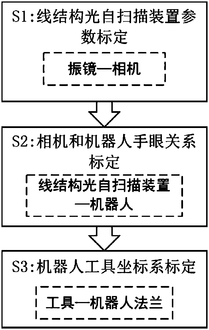
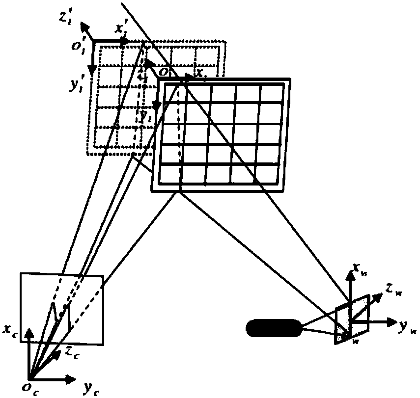

Image

  • Robot positioning device and method based on novel visual guidance
  • Robot positioning device and method based on novel visual guidance
  • Robot positioning device and method based on novel visual guidance

Examples


Embodiment Construction

[0032] The present invention will be further described in detail below in conjunction with the embodiments and the accompanying drawings, but the embodiments of the present invention are not limited thereto.

[0033] A robot positioning device based on a novel visual guidance of the present invention is composed of a line structured light self-scanning device, a robot module and a host computer, wherein:

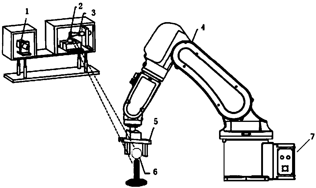
[0034] see figure 1 , the line-structured light self-scanning device includes an industrial camera 1, a vibrating mirror 2, and a laser 3; wherein, the industrial camera 1 captures a plurality of two-dimensional checkerboard target images in different poses within its working range; The galvanometer 2 precisely controls the rotation angle through the voltage signal sent by the host computer 7; the line-structured light plane emitted by the laser 3 is reflected by the galvanometer 2 and projected onto the surface of the target object 6 to form a laser light bar, wherein the c...


PUM


Abstract

The invention discloses a robot positioning device and method based on novel visual guidance. A system device comprises a line structured light self-scanning device, a robot module and an upper computer. The line structured light self-scanning device comprises an industrial camera, a laser and a galvanometric scanner. The robot module comprises a robot body and a robot controller. A system methodis a method for joint calibration of a robot hand-eye relationship and a tool coordinate system. By use of the method, a system enables the industrial robot to locate a target object in a random posture. The robot positioning device and method can be applied to the tasks of grabbing and carrying by the robot.

Description

technical field [0001] The invention relates to an industrial robot positioning system device and method, in particular to a robot positioning device and method based on a novel visual guidance. Background technique [0002] For most robot application scenarios, it is necessary to know the pose of the target object in advance to complete the corresponding task. At present, in the industrial application of robots, the working path of the robot is mostly planned by manual teaching or offline programming. However, this method strictly limits the starting and ending poses of the target object, and can only be mechanically repeated in advance. The planned path and different working objects need to be taught separately to obtain the corresponding teaching files. The highly structured working environment seriously restricts the work efficiency, flexibility and intelligence of the robot, and cannot meet the requirements of the flexible production system. [0003] Robot vision has b...

Claims


Application Information

Patent Timeline
IPC IPC(8): B25J9/16
CPCB25J9/1671B25J9/1661B25J9/1697
Inventor 钟鸿飞覃争鸣
Owner 广州映博智能科技有限公司
Learn More