Liquefied petroleum gas recycling and refining device

A technology of liquefied petroleum gas and refining equipment, which is applied in the petroleum industry, hydrocarbon oil treatment, hydrocarbon distillation, etc., can solve the problems of low utilization rate of vacuum residue oil and decrease in value of vacuum residue oil, and achieve the effect of speeding up the distillation speed

Inactive Publication Date: 2018-06-01
CHENGDU LAIBAO PETROLEUM EQUIP
View PDF0 Cites 0 Cited by
  • Summary
  • Abstract
  • Description
  • Claims
  • Application Information

AI Technical Summary

Problems solved by technology

But at present, the utilization rate of vacuum residue is low, resulting in a significant drop in the value of vacuum residue

Method used


Image

  • Liquefied petroleum gas recycling and refining device

Examples


Embodiment 1

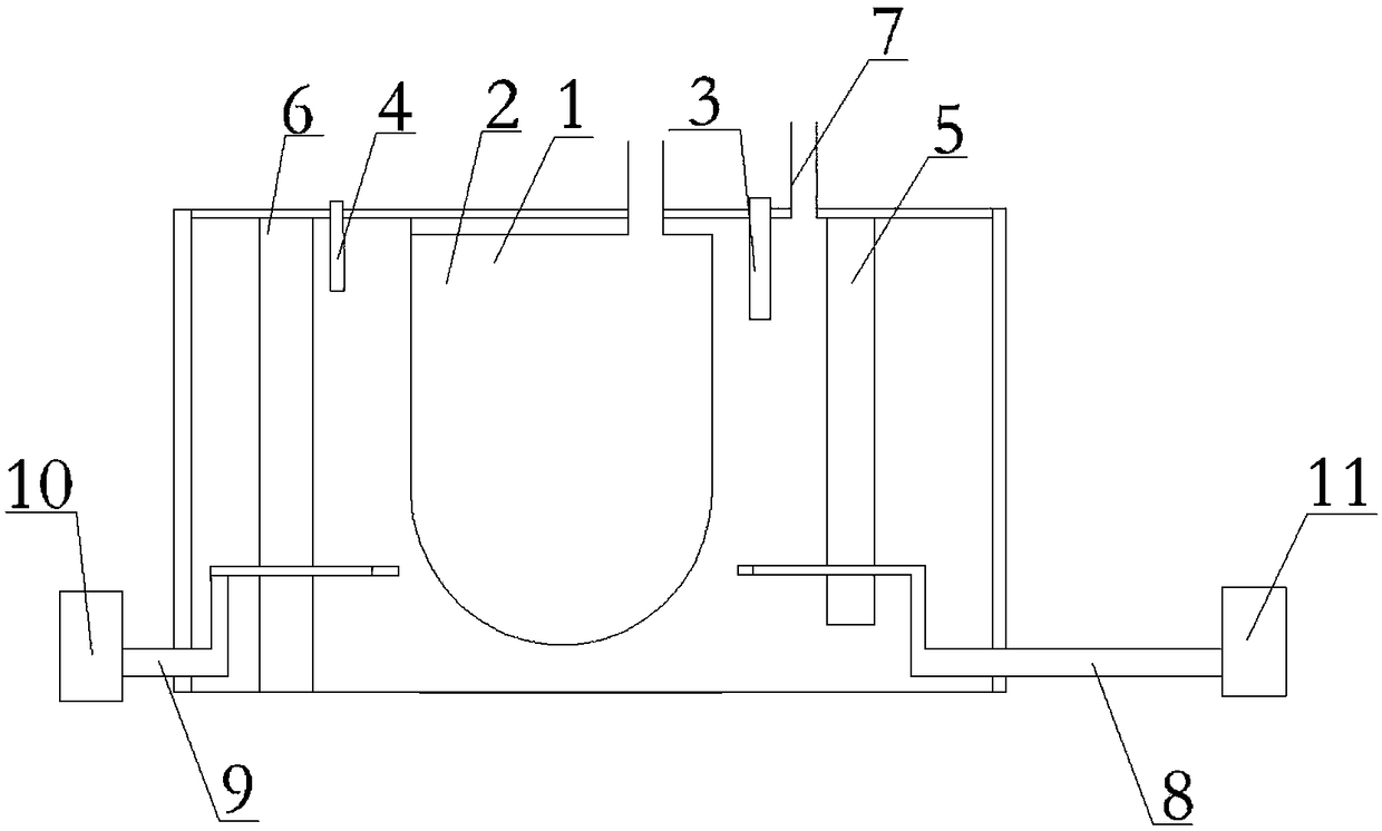
[0020] Such as figure 1 As shown, a recovery and refining device for liquefied petroleum gas comprises a box-type furnace body 1 and a furnace body body 2. One fire-retaining wall 5, the second fire-retaining wall 6, the upper end of the first fire-retaining wall 5 is fixed on the top of box-type furnace body 1, the bottom end of one end box-type furnace body 1 of the second fire-retaining wall 6, the second fire-retaining wall 6 The other end is a free end; one end of the box-type furnace body 1 is provided with a first gas pipeline 8, and one end of the first gas pipeline 8 passes through the first fire wall 5 and extends to the outer surface of the furnace body 2, and the first gas pipeline 8 The other end of gas pipeline 8 is positioned at the outside of chamber furnace body 1;

[0021] The other end of the box-type furnace body 1 is provided with a second gas pipeline 9, and one end of the second gas pipeline 9 passes through the second fire wall 6 and extends to the out...


PUM


Abstract

The invention discloses a liquefied petroleum gas recycling and refining device which comprises a box type furnace body and a furnace body, wherein the furnace body is arranged in the center of the box type furnace body, a first fire barrier wall and a second fire barrier wall are respectively arranged at the two ends of the furnace body, the upper end of the first fire barrier wall is fixed to the top end of the box type furnace body, one end of the second fire barrier wall is fixed to the bottom end of the box type furnace body, and the other end of the second fire barrier wall is the free end, a first gas transmission pipeline is arranged at one end of the box type furnace body, one end of the first gas transmission pipeline penetrates through the first fire barrier wall and extends tothe outer surface of the furnace body, and the other end of the first gas transmission pipeline is arranged outside the box type furnace body. According to the liquefied petroleum gas recycling and refining device disclosed by the technical scheme of the invention, a first through hole and a second through hole are respectively formed in the first fire barrier wall and the second fire barrier wall; furthermore, the first through hole and the second through hole are mainly used for bring convenience to the first gas transmission pipeline and the second gas transmission pipeline, and high temperature gas can reach any position on the surface of the furnace body through the first gas transmission pipeline and the second gas transmission pipeline to fully exchange heat with the furnace body.

Description

technical field [0001] The invention relates to the field of petrochemical industry, in particular to a recovery and refining device for liquefied petroleum gas. Background technique [0002] Residual oil is a kind of liquefied petroleum. Vacuum residual oil is the heaviest component remaining after crude oil has been distilled under atmospheric pressure and vacuum. It is usually in a solid state. According to different properties, it can be used as coking raw material, catalytic raw material, and hydrogenation of residual oil. , solvent deasphalting, visbreaking and other raw materials, among which vacuum residue oil needs to meet certain quality standards as fuel oil, such as sulfur content, ash content, etc. In petroleum refineries, residual oil is often used to process products such as petroleum coke, residual lubricating oil, petroleum asphalt, or as a cracking raw material. In petrochemical production, residual oil can be used to produce syngas or hydrogen through par...

Claims


Application Information

Patent Timeline
Patent Type & Authority Applications(China)
IPC IPC(8): C10G7/00
CPCC10G7/00C10G2300/1077
Inventor 谭正怀
Owner CHENGDU LAIBAO PETROLEUM EQUIP
Why Eureka
Try Eureka