Directional purging system and method

A technology of reversing valve and purging gas, applied in combustion methods, gas fuel burners, indirect carbon dioxide emission reduction, etc., can solve problems such as energy waste, waste, etc., and achieve simple pipeline layout, high pressure, and fire breakout time. short effect

Pending Publication Date: 2018-06-01
SHENWU TECH GRP CO LTD
View PDF0 Cites 2 Cited by
  • Summary
  • Abstract
  • Description
  • Claims
  • Application Information

AI Technical Summary

Problems solved by technology

This part of the gas does not participate in the combustion, which not only causes energy waste, but also brings huge pressure on environmental protection because of the CO component in the gas.
[0007] Therefore, for each reversing, the gaseous fuel in the pipeline from the burner to the reversing device will be disc

Method used


Image

  • Directional purging system and method
  • Directional purging system and method

Examples


Example Embodiment

[0027] The specific implementations of the present invention will be described in more detail below in conjunction with the accompanying drawings and embodiments, so as to better understand the solutions of the present invention and the advantages of various aspects. However, the specific embodiments and examples described below are only for illustrative purposes, rather than limiting the present invention.

[0028] The inventive idea of ​​the present invention is to provide a reversing purge device on the reversing valve, and before each reversing valve is activated, purge gas is introduced to blow the remaining gas in the pipeline into the furnace to make it participate in combustion.
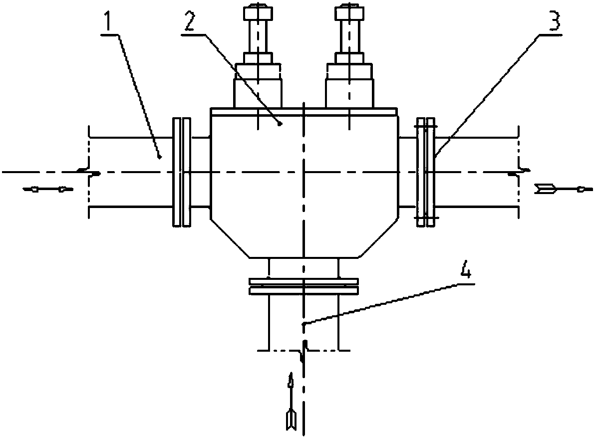
[0029] Such as figure 2 As shown, in the reversing purge system provided by the present invention, the reversing purge system includes a reversing valve 2 and a purge device, wherein the reversing valve 2 includes a gas connection port 21, a flue gas connection port 22, The front pipe interface ...


PUM


Abstract

The invention relates to a directional purging system and method. The directional purging system comprises a reversing valve and a purging device, wherein the reversing valve comprises a gas connecting pipe orifice, a smoke connecting pipe orifice and a burner front pipe joint; the purging device comprises a purging joint and a purging pipe connected in sequence; and the purging joint is connectedto a valve body of the reversing valve, and communicates with the burner front pipe joint. The method comprises the following steps: before the reversing valve enables a burner front pipe to enter asmoke discharge state from gas input, the purging device is started; purging gas is introduced in the purging device to purge the burner front pipe; and when purging is finished, the reversing valve actuates a reversing action, so that the burner front pipe is changed to the smoke discharge state. Residual gas in pipes at each time of purging can be purged into a hearth, so that the CO content inthe smoke is greatly reduced, and the purposes of fuel saving and environmental protection are achieved.

Description

technical field [0001] The invention relates to the technical field of regenerative combustion, in particular to a reversing purge system and method for a regenerative combustion device. Background technique [0002] The regenerative combustion technology alternately switches the air or gas fuel and the flue gas through the reversing device, so that it flows through the heat storage body, which can recover the sensible heat of the high-temperature flue gas to the greatest extent, and the exhaust gas temperature can be reduced below 180 °C , and the combustion-supporting medium or gas fuel can be preheated to above 1000°C to form a new type of flame that is different from the traditional flame, and the temperature distribution in the furnace can be made more uniform by reversing the combustion. [0003] The regenerative burner is a burner with a waste heat recovery device in the regenerator, which is used in pairs to achieve periodic combustion through reversing. One furnace...

Claims


Application Information

Patent Timeline
IPC IPC(8): F23D14/66F23D14/46
CPCF23D14/46F23D14/66Y02E20/34
Inventor 林景龙吴道洪
Owner SHENWU TECH GRP CO LTD
Why Eureka
Try Eureka