
Plane grating interferometer displacement measuring system

A flat grating, displacement measurement technology, applied in measurement devices, instruments, optical devices, etc., can solve the problems of easy interference of measurement signals, complex optical structure, difficult to guarantee accuracy, etc. , the effect of improving the measurement accuracy

Pending Publication Date: 2018-06-01
TSINGHUA UNIV +1
View PDF4 Cites 15 Cited by
  • Summary
  • Abstract
  • Description
  • Claims
  • Application Information

AI Technical Summary

Problems solved by technology

In the research paper "Design and construction of a two-degree-of-freedom linear encoder for nanometric measurement of stage position and straightness. Precision Engineering 34 (2010) 145-155", Japanese scholar GAOWEI proposed a single encoder using the principle of diffraction interference. Frequency two-dimensional grating measurement system, which can realize horizontal and vertical displacement measurement at the same time, but due to the use of single-frequency laser, the measurement signal is susceptible to interference, and the accuracy is difficult to guarantee
Chinese patent document application numbers 201210449244.9 (application date November 09, 2012) and 201210448734.7 (application date November 09, 2012) respectively disclose a heterodyne grating interferometer measurement system, and the readings in the two interferometer measurement systems The head structure uses a quarter-wave plate to change the polarization state of the beam, the optical structure is complex, and the non-ideality of the optical components will lead to measurement errors

Method used


Image

  • Plane grating interferometer displacement measuring system
  • Plane grating interferometer displacement measuring system
  • Plane grating interferometer displacement measuring system

Examples


Embodiment Construction

[0025] The structure, principle and specific implementation of the present invention will be further described in detail below in conjunction with the accompanying drawings.

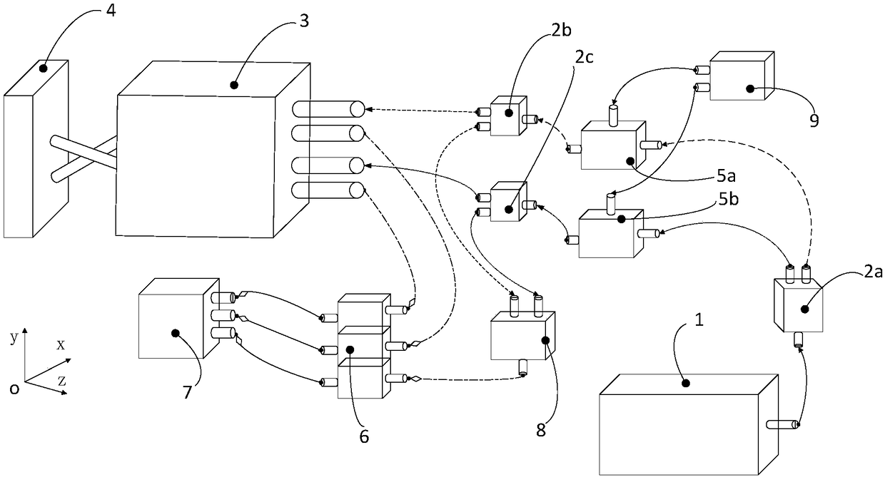
[0026] Please refer to figure 1 , the planar grating interferometer displacement measurement system includes a single-frequency laser 1, a beam splitter, a grating interferometer 3, a planar grating 4, an acousto-optic modulator, a receiver 6 and an electronic signal processing component 7, and the planar grating 4 is a two-dimensional reflection type grating.

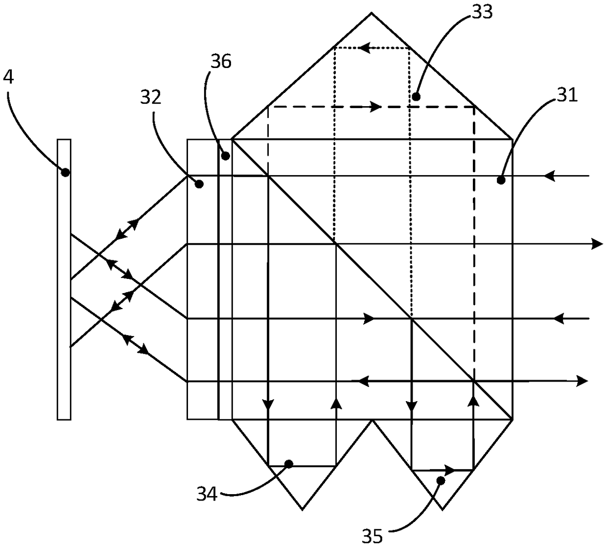
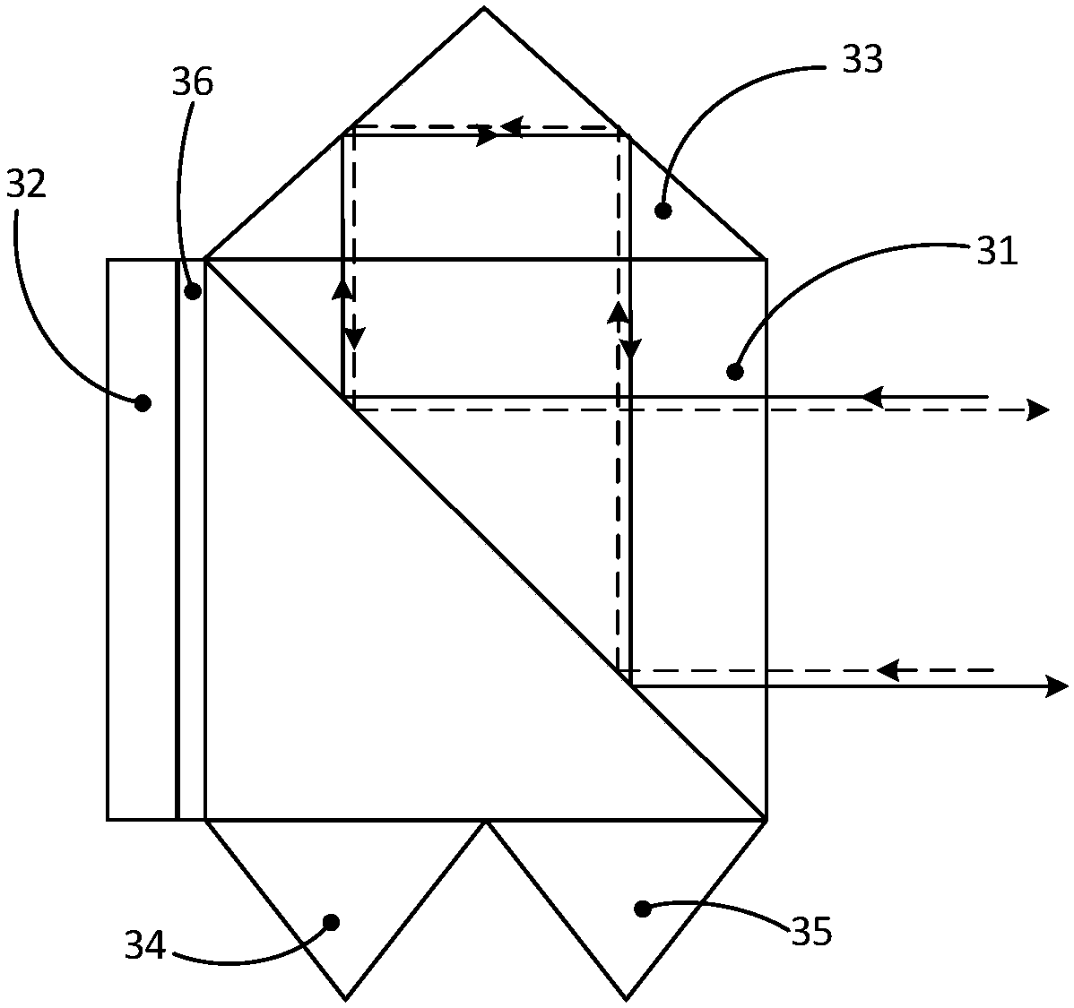
[0027] Please refer to figure 2 , the grating interferometer 3 includes a polarization beam splitter 31, a refractive element 32, a first right-angle prism 33, a second right-angle prism 34 and a third right-angle prism 35, a quarter wave plate 36, and a refractive element 32, wherein the first The right-angle prism 33 is located at the top of the polarization beam splitter, and the second right-angle prism 34 and the third right-angle prism 3...


PUM


Abstract

A plane grating interferometer displacement measuring system comprises a single-frequency laser, beam splitters, acousto-optic modulators, a grating interferometer, a plane grating, a receiver, an electronic signal processing component, an optical fiber coupler and a frequency synthesizer, wherein the grating interferometer comprises a polarizing beam splitter, refractive element, a right-angle prism and a quarter-wave plate. The plane grating interferometer displacement measuring system realizes displacement measurement based on grating diffraction, an optical Doppler effect and an optical beat frequency principle. When the grating interferometer and the plane grating do linear relative motion with two degrees of freedom, the plane grating interferometer displacement measuring system canoutput two pieces of linear displacement. The plane grating interferometer displacement measuring system can realize sub-nanometer or higher resolution and precision, can measure two pieces of lineardisplacement simultaneously, has the advantages of high measurement precision and simple structure, and can improve the comprehensive performances of a workpiece bench when used as a lithography machine ultra-precision workpiece bench position measuring system.

Description

technical field [0001] The invention relates to a displacement measuring system of a plane grating interferometer, in particular to a displacement measuring system of a plane grating interferometer used for measuring the displacement of a workpiece table of a lithography machine. Background technique [0002] As a typical displacement sensor, the grating measurement system is widely used in many electromechanical equipment. The measurement principle of the grating measurement system is mainly based on the Moiré fringe principle and the diffraction interference principle. As a well-developed displacement sensor, the grating measurement system based on the Moiré fringe principle has become the first choice for displacement measurement of many electromechanical equipment due to its long measuring range, low cost, and easy installation and adjustment, but the accuracy is usually on the order of microns, which is common for general industrial applications. [0003] The lithogra...

Claims


Application Information

Patent Timeline
IPC IPC(8): G01B11/02G01B9/02G01D5/26G01D5/38
CPCG01B9/02015G01B9/02055G01B11/02G01D5/266G01D5/268G01D5/38
Inventor 朱煜王磊杰张鸣夏野成荣叶伟楠杨开明倪畅丁思齐贾喆李情情王雨竹
Owner TSINGHUA UNIV
Learn More