Butterfly laser

A laser and butterfly technology, applied in the field of lasers, can solve the problems of complex processing procedures, high processing requirements and low efficiency, and achieve the effect of avoiding magnetic field interference, improving efficiency and ensuring coupling efficiency.

Active Publication Date: 2018-06-01
四川梓冠光电科技有限公司
View PDF7 Cites 2 Cited by
  • Summary
  • Abstract
  • Description
  • Claims
  • Application Information

AI Technical Summary

Problems solved by technology

In order to obtain higher coupling efficiency, the processing requirements are high, the processing procedures are complicated and the efficiency is low

Method used


Image

  • Butterfly laser
  • Butterfly laser
  • Butterfly laser

Examples


Embodiment 1

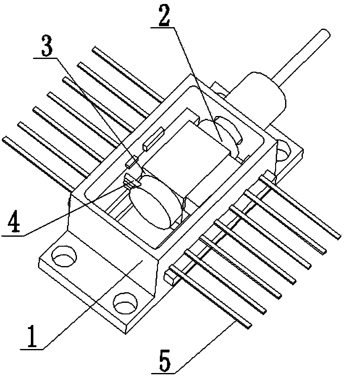
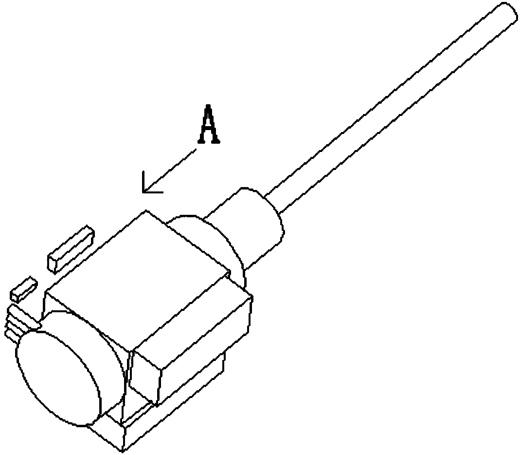
[0025] Such as figure 1 , figure 2 , image 3 , Figure 4 The shown butterfly laser comprises a casing 1 and a laser chip 31, a beam splitter 32, an optical isolator 37, a prism 33, a photodetector 34, a fiber collimator 35, an optical fiber 36, Leads 4 connected to the laser chip, the laser chip, beam splitter, optical isolator 37 , prism, photodetector, fiber collimator, optical fiber, and leads 4 are integrated into a single package structure 2 . The process of integrating and packaging laser chips, beam splitters, optical isolators, prisms, photodetectors, fiber collimators, and optical fibers into a package structure can be realized in many existing factories. The beam splitter divides the laser light from the laser chip into two paths, and one leads to the photodetector. The photodetector detects the light and uses the current to calculate the voltage to identify the level of the laser emitted by the laser chip. The control of the amount of emitted laser light, the ...

Embodiment 2

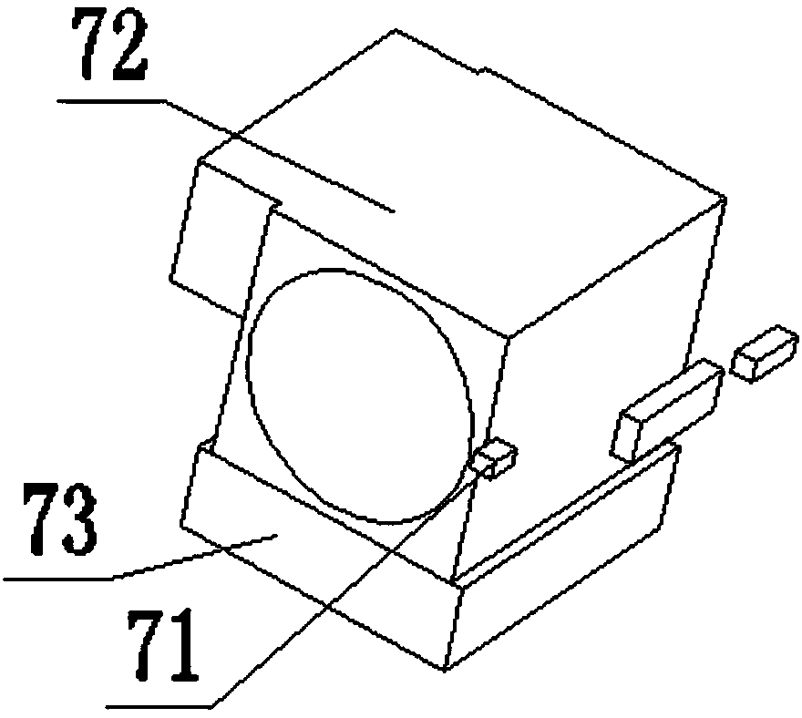
[0027] Based on the structure of the above embodiment, this embodiment refines the above structure, that is, the package structure 2 is fixed in the package 3, and the package 3 is provided with a heating component 72, a cooling component 73 and a temperature detection device for monitoring the temperature 71. The heating component can be realized by using a heat conduction sheet made of superconducting material, so as to control the temperature.

[0028] There are many ways to install the packaging structure. For example, the packaging structure 2 is directly fixed on the package in a cylindrical shape, such as figure 1 shown. On this basis, threads can also be provided outside the package structure 2, and screw holes matching the threads of the package structure 2 can be provided on the package 3 to improve heat conduction efficiency. It is also possible to have two sets of springs in the packaging structure. In order to avoid the influence of the springs on the leads, an ...

Embodiment 3

[0030] The case 1 is provided with pin headers 5, and on the basis of the structure of the above embodiments, it also includes a laser fixture, which is used to clamp the laser to perform tests such as lifespan. Such as Figure 5 As shown, the laser fixture includes a base 61, two rows of bases 62 arranged on the base 61, a needle holder seat 63 arranged on the base 62, and a press for pressing the laser that is movably connected between the bases 62. Rod 64, one end of the base 62 is provided with a pressing bar fixing part 65, the pressing bar fixing part 65 is in an "L" shape, and one end of the pressing bar fixing part 65 is clamped in the through groove at the end of the base 62 66 and the other end is clamped in the guide groove 67 on the base 61, the other end of the pressure bar fixing member 65 is fixed with a guide piece perpendicular to the end, the guide piece is connected to the guide groove 67 Spring is arranged, and this spring has the active force that makes g...


PUM


Abstract

The invention discloses a butterfly laser, and the laser comprises a shell, a laser chip, a beam splitter, an optical isolator, a prism, an optical detector, an optical fiber collimator, an optical fiber, and a lead wire connected to the laser chip, wherein the laser chip, the beam splitter, the optical isolator, the prism, the optical detector, the optical fiber collimator, the optical fiber andthe lead wire are disposed in the shell. The laser chip, the beam splitter, the optical isolator, the prism, the optical detector, the optical fiber collimator, the optical fiber and the lead wire areintegrated into a single package structure. According to the invention, the important parts of the laser are independently integrated and packaged, and then are combined with the shell, thereby guaranteeing the coupling efficiency of the laser, lowering the requirements for the processing technology, improving the efficiency. Moreover, the magnetic field interference can be reduced or avoided, the impedance is reduced, the precision of the laser is improved, and the laser is enabled to meet the application demands of the military industry.

Description

technical field [0001] The invention relates to the technical field of lasers, in particular to a butterfly laser. Background technique [0002] At present, the optical transmitter component is the core device of modern optical fiber communication. High-speed optical transmitters of 10Gb / s and above are usually packaged in a butterfly package to improve the high-frequency performance of the device. The existing butterfly laser includes a casing, a thermistor placed in the casing, a laser chip and other components. The space in the casing is narrow, and each component needs to be packaged in the casing during processing, and the packaging accuracy is related to the coupling efficiency of the butterfly laser. In order to obtain higher coupling efficiency, the processing requirements are high, the processing procedures are complex and the efficiency is low. Contents of the invention [0003] The present invention provides a butterfly laser in order to solve the above techni...

Claims


Application Information

Patent Timeline
Patent Type & Authority Applications(China)
IPC IPC(8): G02B6/42
Inventor 梁联长
Owner 四川梓冠光电科技有限公司
Why Eureka
Try Eureka