Electric and bag-type composite dust removing device and treatment method thereof

A combination technology of dust removal device and electric bag, which is applied in the direction of combination device, separation method, chemical instrument and method, etc., can solve the problems of uneven distribution of flow field of bag filter, increase of filter bag resistance, and decrease of filter bag life, and achieve Reasonable use of the factory use area, the use of the factory use area, and the effect of increasing the residence time

Inactive Publication Date: 2018-06-05
INST OF PROCESS ENG CHINESE ACAD OF SCI
View PDF6 Cites 3 Cited by
  • Summary
  • Abstract
  • Description
  • Claims
  • Application Information

AI Technical Summary

Problems solved by technology

[0006] Aiming at the problems of reduced service life of the filter bag existing in the electric bag composite dust collector with front and rear bags, uneven distribution of the flow field inside the bag filter, increased resistance of the filter bag, and influence on the dust removal efficiency, the present invention provides an electric dust collector. Bag compound dust removal device and its treatment method

Method used


Image

  • Electric and bag-type composite dust removing device and treatment method thereof
  • Electric and bag-type composite dust removing device and treatment method thereof
  • Electric and bag-type composite dust removing device and treatment method thereof

Examples


Embodiment 1

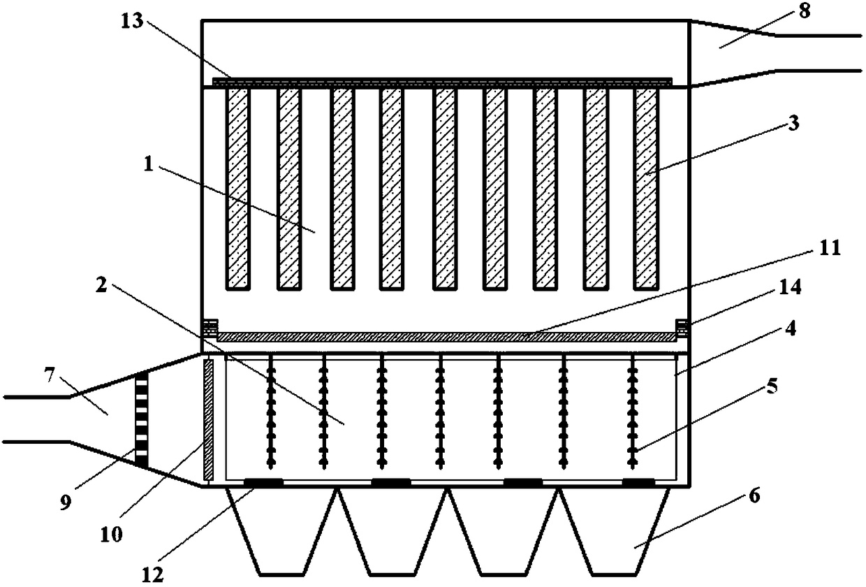
[0065] This embodiment provides a kind of electric bag composite dedusting device and its processing method, such as Figure 1-Figure 4 As shown, the electrostatic bag composite dust removal device includes an electrostatic dust removal area 2 placed at the lower part of the device and a bag dust removal area 1 placed above the electrostatic dust removal area 2. Gas inlet 7, the top of the device opposite to the flue gas inlet 7 is provided with a flue gas outlet 8 connected to the bag dust removal area 1, and a first deflector is provided between the flue gas inlet 7 and the electrostatic precipitator area 2 10. A second deflector 11 is set between the electrostatic precipitator area 2 and the bag filter area 1 .

[0066] Wherein, the height of the bag dust removal area 1 is twice the height of the electrostatic precipitator area 2, a bottom ash hopper 6 is set under the electrostatic precipitator area 2, and a first rapping cleaning machine is set between the electrostatic p...

Embodiment 2

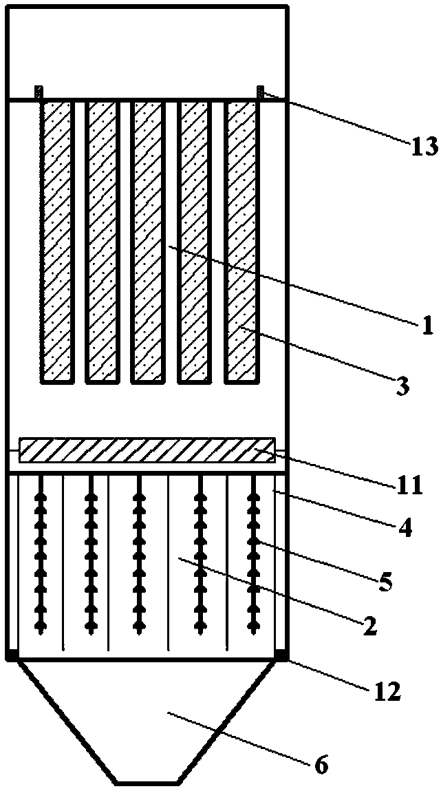
[0076] This embodiment provides an electric bag composite dedusting device and its processing method. The electric bag composite dedusting device includes an electrostatic precipitator area 2 placed at the bottom of the device and a cloth bag dedusting area 1 placed above the electrostatic precipitator area 2. The bottom side of the device is provided with a flue gas inlet 7 connected to the electrostatic precipitator area 2, and the top side of the device opposite to the flue gas inlet 7 is provided with a flue gas outlet 8 connected to the bag dust removal area 1. The flue gas inlet 7 A first guide plate 10 is provided between the electrostatic precipitator area 2 and a second guide plate 11 is provided between the electric precipitator area 2 and the bag dust removal area 1 .

[0077] Wherein, the height of the bag dust removal area 1 is twice the height of the electrostatic precipitator area 2, a bottom ash hopper 6 is set under the electrostatic precipitator area 2, and a ...

Embodiment 3

[0084] This embodiment provides an electric bag composite dust removal device and its processing method. The structure of the electric bag composite dust removal device refers to the structure in Example 1, the only difference is:

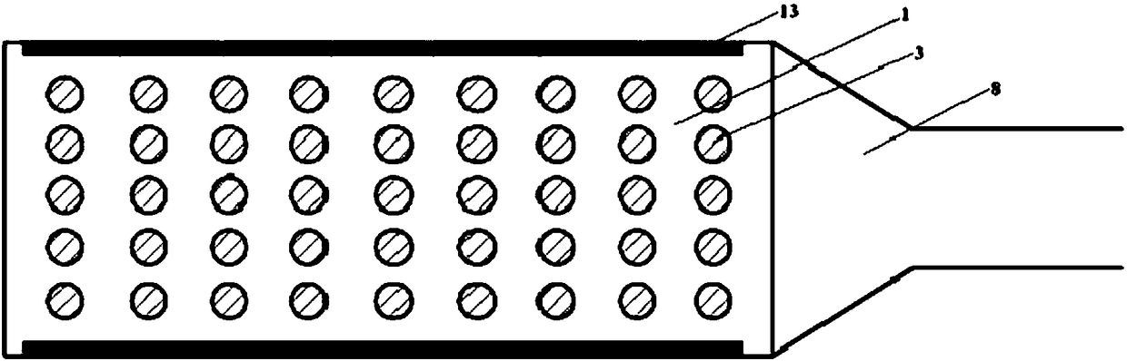
[0085] The height of the bag dust removal area 1 is 4 times the height of the electrostatic precipitator area 2; the cathode line 5 array includes 1200 cathode lines 5, 40 cathode lines 5 are set in each row, and 30 cathode lines 5 are set in each column; the filter bag 3 array includes 750 filter cloth bags 3, each row is provided with 30 filter cloth bags 3, and each row is provided with 25 filter cloth bags 3; The included angle of the horizontal line is 135°, so that the airflow direction of the flue gas entering the electrostatic precipitator area 2 is 135° of the included angle of the horizontal line, and the residence time of the flue gas in the electrostatic precipitator area 2 is increased by 3 seconds; the second deflector 11 is an airflow...


PUM


Abstract

The invention provides an electric and bag-type composite dust removing device and a treatment method thereof. The electric and bag-type composite dust removing device comprises an electric dust removing zone arranged at the lower part thereof and a bag-type dust removing zone arranged above the electric dust removing zone, wherein a flue gas inlet connected with the electric dust removing zone isformed in one side of the bottom of the electric and bag-type composite dust removing device; a flue gas outlet connected with the bag-type dust removing zone is formed in one side, opposite to the flue gas inlet, of the top of the electric and bag-type composite dust removing device; a first flow guiding plate is arranged between the flue gas inlet and the electric dust removing zone; and a second flow guiding plate is arranged between the electric dust removing zone and the bag-type dust removing zone. In the electric and bag-type composite dust removing device, flue gas is charged and trapped by the electric dust removing zone and upwardly enters the bag-type zone for dust removal, so that the flue gas is prevented from rightly scouring a filter cloth bag, the service life of the filter cloth bag is prolonged, the floor area of the electric and bag-type composite dust removing device is reduced, and the factory using area is reasonably utilized; through arrangement of the gas flowguiding plates, the flow direction of a gas flow can be changed, the residence time of the flue gas in the electric dust removing zone can be prolonged, the flue gas flow can be prevented from forminga dead zone in the electric dust removing zone, and the dust removing efficiency can be improved.

Description

technical field [0001] The invention belongs to the technical field of air pollutant cleaning, relates to an electric bag composite dedusting device and a treatment method thereof, in particular to an electric bag for effectively removing particulate matter in flue gas pollutants to meet ultra-low emission standards Composite dust removal device and its processing method. Background technique [0002] At present, the control of particulate matter in air pollutants has received extensive attention. Efficient dust removal devices include electrostatic precipitators, bag filters, and electrostatic bag composite precipitators. Among them, the electrostatic precipitator has the advantages of small running resistance, wide application range and convenient equipment maintenance, but its removal efficiency for PM10 is low. The bag filter has a high removal efficiency for PM10, but it is limited by the overall resistance. The electric bag composite dust collector generally adopts t...

Claims


Application Information

Patent Timeline
Patent Type & Authority Applications(China)
IPC IPC(8): B01D50/00
CPCB01D50/00
Inventor 朱廷钰王雪孙彬彬
Owner INST OF PROCESS ENG CHINESE ACAD OF SCI
Why Eureka
Try Eureka