Antenna installation seat and antenna

A mounting seat and antenna technology, which is applied in the direction of antenna support/mounting device, antenna, antenna grounding switch structure connection, etc., can solve the problems of low elevation angle gain difference, antenna beam width is not wide, low gain, etc., to improve low elevation angle Adjustable gain, beam width, and strong structural consistency

Inactive Publication Date: 2018-06-05
HARXON CORP
View PDF6 Cites 5 Cited by
  • Summary
  • Abstract
  • Description
  • Claims
  • Application Information

AI Technical Summary

Problems solved by technology

[0003] The bandwidth advantage of stacked microstrip antennas is not obvious, the antenna beam width is not wide, and the gain at low elevation angles is poor. The width is not wide, the gain is poor at low elevation angles, the structure assembly is also more complicated, and the cost is higher; the beam width of the multi-frequency helical antenna is wider, but the gain is lower
[0004] In the use of GNSS antennas, the problem directly caused by the above-mentioned low elevation angle gain difference is that the anti-multipath effect is relatively poor, that is, the antenna ranging error increases, resulting in insufficient positioning accuracy.

Method used


Image

  • Antenna installation seat and antenna
  • Antenna installation seat and antenna
  • Antenna installation seat and antenna

Examples


Embodiment Construction

[0055]In order to make the purposes, technical solutions and advantages of the embodiments of the present application clearer, the technical solutions in the embodiments of the present application will be clearly and completely described below in conjunction with the drawings in the embodiments of the present application. Obviously, the described embodiments It is a part of the embodiments of this application, but not all of them. Based on the embodiments in the present application, all other embodiments obtained by persons of ordinary skill in the art without making creative efforts belong to the protection scope of the present application.

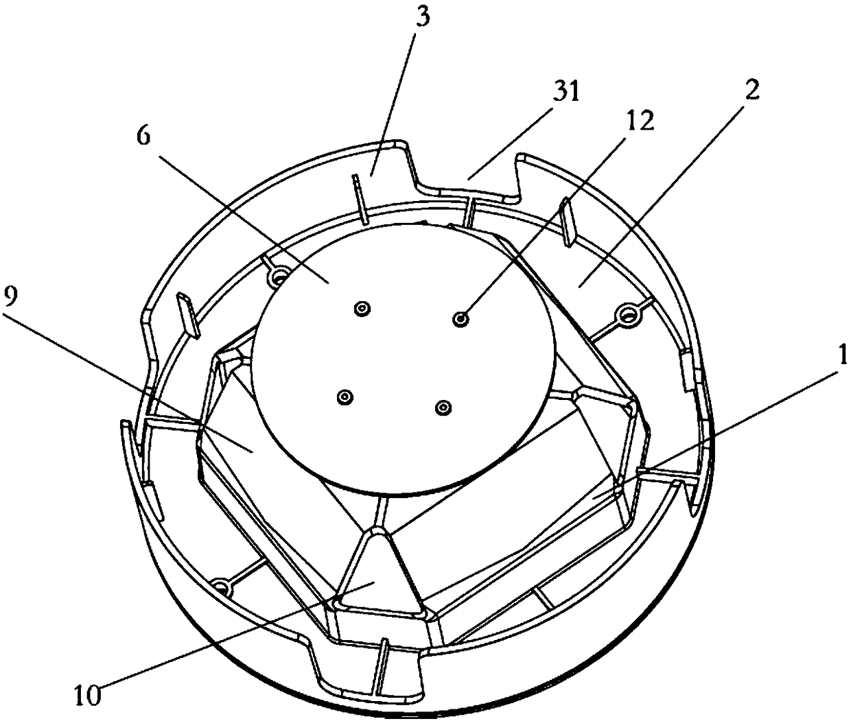
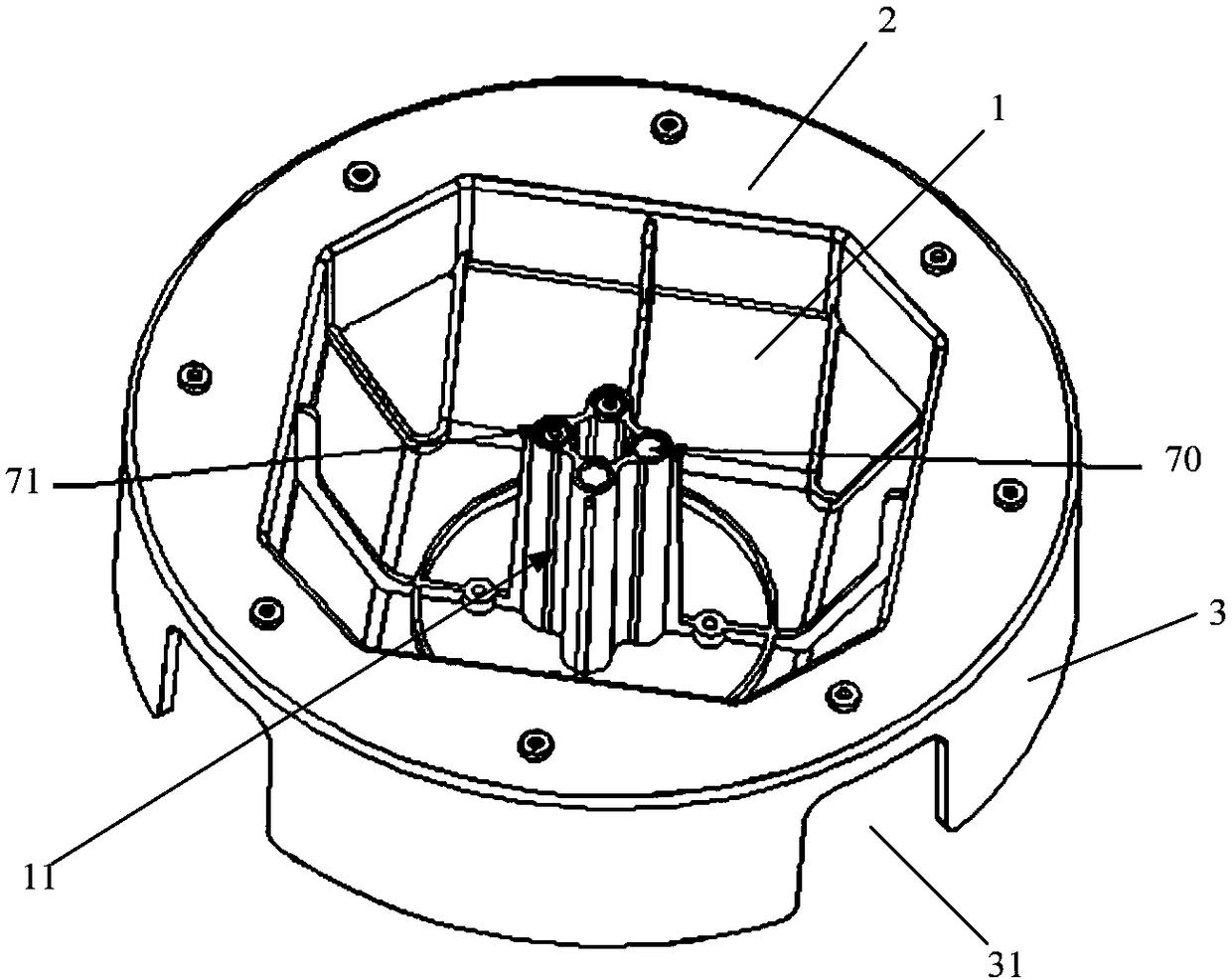
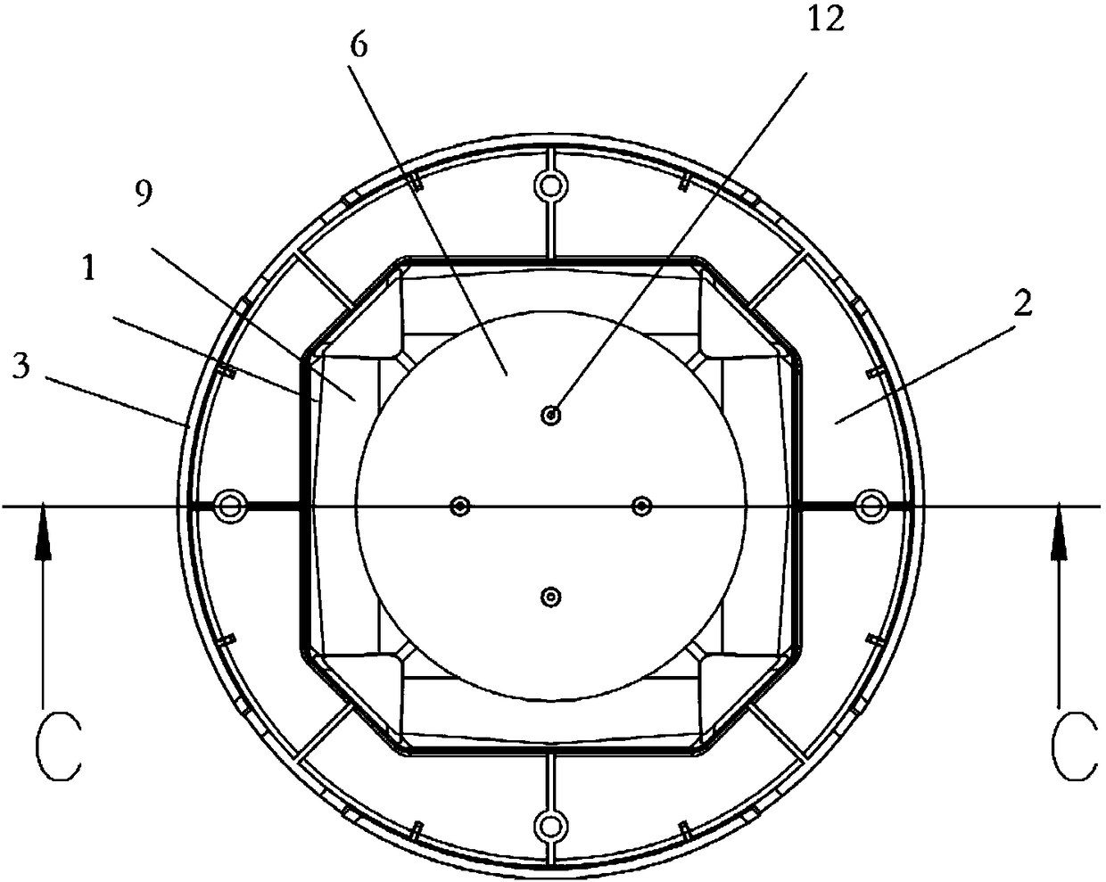
[0056] figure 1 It is a schematic structural diagram of the antenna provided in the embodiment of the present application, figure 2 for figure 1 Schematic diagram of the back structure. image 3 for figure 1 top view of Figure 4 for image 3 Schematic cross-sectional view of plane C-C; Figure 5 for figure 1 right view of Fig...


PUM


Abstract

The invention relates to an antenna installation seat and an antenna, and the antenna installation seat comprises an antenna substrate, a fixed plate, and an annular reflection plate. The antenna substrate is of a bowl-shaped structure, and the edge of the opening of the bowl-shaped structure is fixed with the fixed plate. The annular reflection plate is located on the fixed late and is fixed withthe fixed plate. The antenna reflection plate and the antenna substrate are located on the same side surface of the fixed plate. The interior of the bowl-shaped structure is provided with a feed support seat. Compared with a conventional product technology, the antenna is simple in assembly, is higher in structural consistency, and is higher in low-elevation gain.

Description

technical field [0001] The present application relates to the technical field of antennas, in particular to an antenna mount and an antenna. Background technique [0002] The existing multi-frequency circularly polarized GNSS (Global Navigation Satellite System, global satellite navigation system) antennas are usually in the form of laminated microstrip antennas, metal half-wave array antennas, and helical antennas. Technically speaking, laminated microstrip antennas and Metal half-wave array antennas have achieved a certain frequency bandwidth function, but there are still many problems. [0003] The bandwidth advantage of stacked microstrip antennas is not obvious, the antenna beam width is not wide, and the gain at low elevation angles is poor. The width is not wide, the gain is poor at low elevation angles, the structure assembly is more complicated, and the cost is higher; the beam width of the multi-frequency helical antenna is wider, but the gain is lower. [0004] ...

Claims


Application Information

Patent Timeline
Patent Type & Authority Applications(China)
IPC IPC(8): H01Q1/12H01Q15/14H01Q1/50
CPCH01Q1/12H01Q1/50H01Q15/14H01Q1/38H01Q19/108H01Q21/26
Inventor 吴文平吴仕伟张婕
Owner HARXON CORP
Why Eureka
Try Eureka