A low-temperature drift oscillator and method for obtaining low-temperature drift clock frequency

A clock frequency and low-temperature drift technology, which is applied in the field of low-temperature drift oscillators and low-temperature drift clock frequency, can solve problems such as poor product consistency, high process consistency requirements, and impact on oscillator frequency temperature drift, etc., to achieve high power supply suppression Ratio, wide adjustable range, easy to achieve effect

Active Publication Date: 2021-04-09
SHANGHAI CHIPON MICRO ELECTRONICS CO LTD
View PDF5 Cites 0 Cited by
  • Summary
  • Abstract
  • Description
  • Claims
  • Application Information

AI Technical Summary

Problems solved by technology

[0002] In the prior art, the oscillator usually adopts a ring or RC charge-discharge oscillation structure. The frequency of the ring oscillator is closely related to the device temperature characteristics and process of the power supply and inverter. Due to the large difference between chips and the temperature drift cannot be calibrated , leading to poor product consistency
Because the RC oscillator uses the bandgap voltage to generate the charging current, the final frequency is only related to the temperature characteristics of the resistor R and the capacitor C. In fact, both the resistor R and the capacitor C have a temperature drift of about 10%, even if they are used in combination The resistance of positive and negative temperature drift can be reduced. Generally, the difference between chips will be higher than 2%, and when calibrating the temperature drift, it will also affect the absolute value of the oscillator frequency; and when calibrating the absolute value of the oscillator frequency, it will be Temperature drift that affects the oscillator frequency
Because the existing oscillator structure cannot calibrate the temperature drift and the absolute value of the frequency independently, the final temperature drift between chips must be guaranteed by the process, which requires high process consistency.

Method used


Image

  • A low-temperature drift oscillator and method for obtaining low-temperature drift clock frequency
  • A low-temperature drift oscillator and method for obtaining low-temperature drift clock frequency

Examples


Embodiment Construction

[0023] The present invention is described in detail below in conjunction with accompanying drawing and specific embodiment:

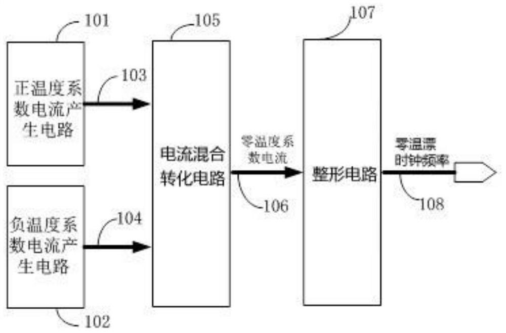
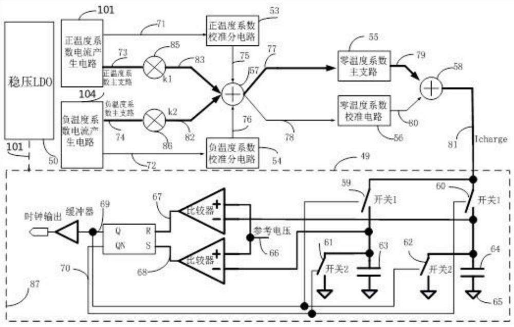
[0024] Such as figure 1 As shown, a low-temperature drift oscillator includes a positive temperature coefficient current generating circuit 101, a negative temperature coefficient current generating circuit 102, a current mixing conversion circuit 105 and a capacitance shaping circuit 107, and the positive temperature coefficient current generating circuit 101 generates a current mirror through a current mirror. The positive temperature coefficient main branch 73 and a positive temperature current calibration branch 71, the negative temperature coefficient current generation circuit 102 produces a negative temperature coefficient main branch 74 and a negative temperature current calibration branch 71 through the current mirror; the positive temperature coefficient main Branch 73, positive temperature and current calibration branch 71, negative temperatu...


PUM


Abstract

The invention relates to a low-temperature drift oscillator, which belongs to the technical field of oscillators. A low-temperature drift oscillator and a method for obtaining a low-temperature drift clock frequency, characterized in that it includes a positive temperature coefficient current generation circuit, a negative temperature coefficient current generation circuit, a current mixing conversion circuit and a capacitance shaping circuit, and the positive temperature coefficient current generation circuit passes through The current mirror generates a positive temperature coefficient main branch and a positive temperature current calibration branch, and the negative temperature coefficient current generation circuit generates a negative temperature coefficient main branch and a negative temperature current calibration branch through the current mirror; through the current mixing conversion circuit After mixing, the zero temperature coefficient current is obtained, and the zero temperature coefficient current is adjusted according to the needs, and then the constant capacitance in the capacitance shaping circuit is charged and discharged to obtain different low-temperature drift clock frequencies. The invention utilizes the positive temperature curve and the negative temperature curve of the current to correct the temperature drift of the oscillator, which has higher accuracy and is easier to adjust than using other forms of circuits to control the temperature drift.

Description

technical field [0001] The invention relates to an oscillator, in particular to a low-temperature drift oscillator and a method for obtaining a low-temperature drift clock frequency. Background technique [0002] In the prior art, the oscillator usually adopts a ring or RC charge-discharge oscillation structure. The frequency of the ring oscillator is closely related to the device temperature characteristics and process of the power supply and inverter. Due to the large difference between chips and the temperature drift cannot be calibrated , resulting in poor product consistency. Because the RC oscillator uses the bandgap voltage to generate the charging current, the final frequency is only related to the temperature characteristics of the resistor R and the capacitor C. In fact, both the resistor R and the capacitor C have a temperature drift of about 10%, even if they are used in combination The resistance of positive and negative temperature drift can be reduced. Genera...

Claims


Application Information

Patent Timeline
Patent Type & Authority Patents(China)
IPC IPC(8): H03K3/011
CPCH03K3/011
Inventor 冯旭丁晓斌常成星成学斌朱少华孙双豪
Owner SHANGHAI CHIPON MICRO ELECTRONICS CO LTD
Why Eureka
Try Eureka