Pure pneumatic power-assisted mechanical arm device

A robotic arm, pure gas technology, applied in the directions of manipulators, claw arms, conveyor objects, etc., can solve the problems of high labor intensity, low safety factor, low turnover efficiency of workers, etc., to achieve good promotion and application prospects, reduce labor intensity, The effect of improving production efficiency

Pending Publication Date: 2018-06-12
ZHENGZHOU SANKI PETROLEUM EQUIP MFGCO
View PDF0 Cites 5 Cited by
  • Summary
  • Abstract
  • Description
  • Claims
  • Application Information

AI Technical Summary

Problems solved by technology

[0004] In view of the shortcomings in the above-mentioned background technology, the present invention proposes a purely pneumatic power-assisted mechanical arm device, which solves the problems of low moving and turning efficiency, high labor intensity and low safety factor of the self-priming gear oil pump in the fuel dispenser manufacturing process in the prior art. technical issues

Method used


Image

  • Pure pneumatic power-assisted mechanical arm device
  • Pure pneumatic power-assisted mechanical arm device
  • Pure pneumatic power-assisted mechanical arm device

Examples


Embodiment 2

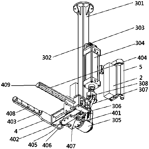
[0023] Embodiment 2, a purely pneumatic power-assisted mechanical arm device, the pneumatic clamp 4 includes a clamp connecting plate 401 fixedly arranged on the turning shaft 311, a slide rail 402 is fixedly arranged on the clamp connecting plate 401, and one end of the slide rail 402 is fixed A first claw 403 is provided, and a second claw 404 is movably provided at the other end. The second claw 404 is fixedly arranged on a sliding frame 405 slidingly matched with the slide rail 402 . The frame 405 is a clamping cylinder 406 that slides in the slide rail 313 , and the control unit 2 also includes a clamping control valve 202 that controls the action of the clamping cylinder 406 . The clamping cylinder 406 drives the second jaw 404 to move while the first jaw 403 is fixed, not only can clamping and unfolding of the fixture be achieved, but also only one jaw has a simple and compact structure and is convenient for production.

[0024] Other structures of this embodiment are t...

Embodiment 3

[0025] Embodiment 3, a purely pneumatic power-assisted mechanical arm device, the turning link 307 is arc-shaped, the transmission gear 306 is a sector gear, and the arc-shaped turning link 307 and the sector gear are integrated. The turning connecting rod 307 is arranged in an arc shape, which can evenly push the transmission gear 306 to rotate with the action of the turning cylinder 304, and then make the turning shaft 311 evenly rotate, and can accurately stop at different positions to facilitate processing of workpieces.

[0026] Other structures of this embodiment are the same as those of Embodiment 1.

Embodiment 4

[0027] Embodiment 4, a purely pneumatic power-assisted mechanical arm device, the limit structure includes two bolt seats 701 arranged on the outside of the turning shaft seat 305, and the two bolt seats 701 are arranged in the same horizontal plane and are left and right symmetrical. Limiting bolts 702 are arranged in the bolt seats 701, the shaft end of the turning shaft 311 is fixedly provided with a connecting flange 703, the connecting flange 703 is fixedly connected with the fixture connecting plate 401, and one side of the connecting flange 703 is provided with a limiting bolt. 702 blocks the limit block 704 that cooperates. The setting of the connecting flange 703 can fully ensure the reliability of the connection between the fixture connecting plate 401 and the turning shaft 311; the limit structure is designed as a form of cooperation between the limit bolt 702 and the limit block 704, which can not only realize the rotation of the turning shaft 311 Limit, and the li...


PUM


Abstract

The invention discloses a pure pneumatic power-assisted mechanical arm device. The technical problems that in the prior art, the moving and overturning efficiency of a self-suction type gear oil pumpis low in the manufacturing process of an oiling machine, the labor intensity of workers is high, and the safety coefficient is low are solved. The device comprises a universal mechanical arm, a control unit and an overturning mechanism. The overturning mechanism comprises a clamp support, a pneumatic clamp and a pneumatic driving mechanism. The pneumatic driving mechanism comprises an overturningair cylinder, wherein the air cylinder is connected with the clamp support, the overturning air cylinder is hinged to an overturning connecting rod, the end part of the clamp support is fixedly connected with an overturning shaft seat, a transmission gear connected with the overturning connecting rod is arranged in the overturning shaft seat, and an overturning rotating shaft which is in transmission connection with the transmission gear is arranged below the overturning shaft seat, the pneumatic clamp is arranged on the overturning rotating shaft, and a limiting structure is arranged on theoverturning shaft seat. The device has the advantages of being simple and compact in structure, strong in compatibility, convenient and flexible to operate, and capable of replacing the clamp, and having a good popularization and application prospect.

Description

technical field [0001] The invention relates to the technical field of boosting auxiliary devices, in particular to a purely pneumatic power-assisted mechanical arm device. Background technique [0002] The robotic arm refers to a high-precision robotic arm. The robotic arm is a complex system with multiple inputs and multiple outputs, highly nonlinear, and strong coupling. Because of its unique operational flexibility, it has been widely used in industrial assembly, safety explosion-proof and other fields. The manipulator is a complex system with uncertainties such as parameter perturbation, external disturbance and unmodeled dynamics. Therefore, there are uncertainties in the modeling model of the manipulator. For different tasks, it is necessary to plan the motion trajectory of the joint space of the manipulator, thereby cascading to form the end pose. Different mechanical arms can achieve different functions, but the existing mechanical arms have complex power structur...

Claims


Application Information

Patent Timeline
IPC IPC(8): B65G47/90B25J18/00B25J15/08B25J15/00
CPCB65G47/90B25J15/00B25J15/08B25J18/00
Inventor 吴军峰黄志勇吴祖坤王占鹏胡瑞超
Owner ZHENGZHOU SANKI PETROLEUM EQUIP MFGCO
Why Eureka
Try Eureka