Railway liner plate for vibration reduction and noise reduction and preparation method of railway liner plate

A technology for railway and backing plates, which is applied in the field of shock-absorbing and noise-reducing railway backing plates and its preparation, which can solve problems affecting the shock-absorbing effect and service life of railway backing plates, material damage, etc., to achieve uniform force and improve impact resistance The effect of high performance and strong pressure resistance

Inactive Publication Date: 2018-06-12
武汉鼎瑞新材料有限责任公司
View PDF4 Cites 4 Cited by
  • Summary
  • Abstract
  • Description
  • Claims
  • Application Information

AI Technical Summary

Problems solved by technology

However, since the railway backing board needs to work in a large load, dynamic, and high-frequency vibration environment for a long time, the railway backing board made of the above-mentioned polyurethane foa

Method used


Image

  • Railway liner plate for vibration reduction and noise reduction and preparation method of railway liner plate
  • Railway liner plate for vibration reduction and noise reduction and preparation method of railway liner plate
  • Railway liner plate for vibration reduction and noise reduction and preparation method of railway liner plate

Examples


Example Embodiment

[0055] Example one

[0056] Put 98g polystyrene particles and 2g expanded microspheres into the injection molding machine, the selected expanded microsphere density is 0.022g / cm 3 , The particle diameter is 120μm, and the screw temperature is set to 120℃, so that the material stays in the mold for 8 minutes.

[0057] Cut the product into the size of the standard railway backing plate in the current rail; take two pieces of products, and evenly coat the molten polyurethane hot melt adhesive on one side of them, and pass the polyurethane hot melt adhesive layer of the two pieces of products after vitrification The buffer layer is glued.

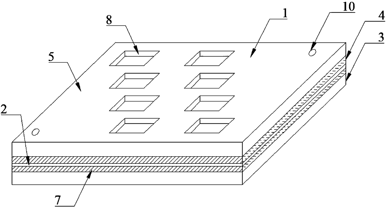
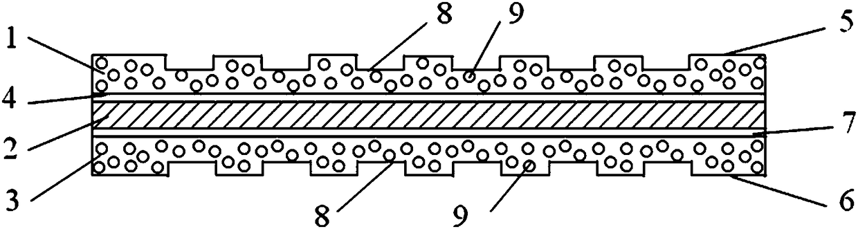
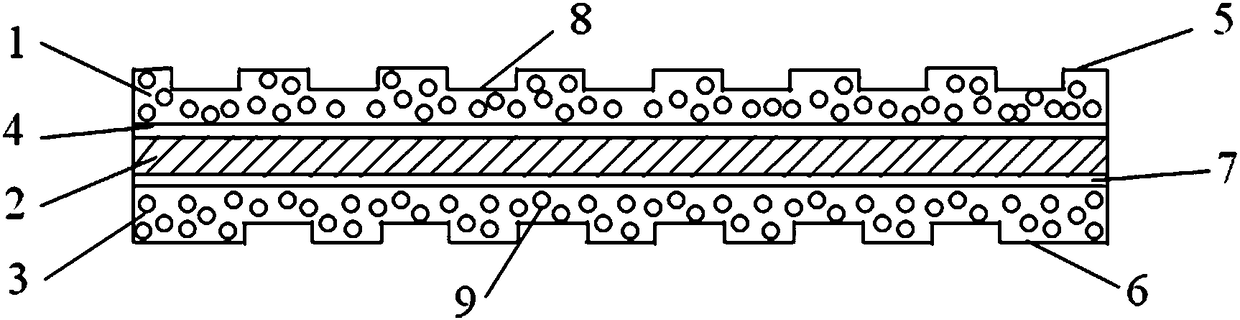
[0058] The structure of the railway pad in this embodiment is as figure 1 As shown, it is a multi-layer structure glued to each other, and from top to bottom are the upper surface layer 1, the first polyurethane hot melt adhesive layer 4, the buffer layer 2, the second polyurethane hot melt adhesive layer 3, and the lower layer 6 in order.

[0059] Amo...

Example Embodiment

[0061] Example two

[0062] Put 99.5g of polycarbonate particles and 0.5g of expanded expanded microspheres into the injection molding machine. The density of the selected expanded microspheres is 0.028g / cm 3 , The particle diameter is 80μm, and the screw temperature is set to 150℃, so that the material stays in the mold for 10 minutes.

[0063] The shape and structure of the obtained railway backing plate are the same as the first embodiment.

Example Embodiment

[0064] Example three

[0065] Put 98g methyl methacrylate particles and 2g expanded expanded microspheres into the injection molding machine. The selected expanded microsphere density is 0.025g / cm 3 , The particle diameter is 100μm, the screw temperature is set to 130℃, so that the material stays in the mold for 9min.

[0066] The shape and structure of the obtained railway backing plate are the same as the first embodiment.


PUM

PropertyMeasurementUnit
Densityaaaaaaaaaa
Diameteraaaaaaaaaa
Thicknessaaaaaaaaaa

Abstract

The invention discloses a railway liner plate for vibration reduction and noise reduction, which relates to the field of railway vibration reduction parts. The railway liner plate for the vibration reduction and noise reduction comprises an upper surface layer and a lower surface layer which are made of 98 to 99.5 parts by weight of viscous resin and 0.5 to 2 parts of expansion microspheres, wherein the viscous resin comprises polyester, polyolefin and liquid rubber, and a shaping temperature of the expansion microspheres is higher than a melting temperature of the viscous resin. The railway liner plate for the vibration reduction and noise reduction has excellent elasticity, high vibration absorption capacity, good damping performance and excellent damping effect, and the absorbed energywhen in stress is large; and the railway liner plate also has the advantages of oil resistance, wear resistance, chemical corrosion resistance, radiation resistance and the like, and is small in compression deformation, high in mechanical strength, good in electric insulation performance and widely applicable to the high-speed railway tracks.

Description

Technical field [0001] The invention relates to the field of railway shock absorption devices, in particular to a railway pad for shock absorption and noise reduction and a preparation method thereof. Background technique [0002] With the rapid development of my country's economy, intercity rail transit and high-speed railways have also developed rapidly. Due to the increase in train running speed, the impact force and impact frequency on the track are naturally increased. In order to ensure the smooth running of the train, the ordinary shock-absorbing component-rubber pad previously used can no longer meet the speed increase requirements. Therefore, it is particularly important and urgent to develop and produce materials with higher shock absorption performance for high-speed railway shock absorption components. [0003] At present, there have been new railway pads made of polyurethane or rubber foam materials instead of ordinary shock-absorbing components-rubber pads. These new...

Claims


Application Information

Patent Timeline
IPC IPC(8): C08J9/236C08G18/48C08G18/79C08G18/32C08G18/10B32B3/30B32B27/40B32B27/06B32B27/00B32B7/12
CPCB32B3/30B32B5/18B32B7/12B32B27/065B32B2250/40B32B2266/0278B32B2307/10B32B2307/51B32B2307/552B32B2307/558B32B2307/56C08G18/10C08G18/4854C08G18/79C08G2350/00C08J9/236C08J2205/052C08J2325/06C08J2333/12C08J2369/00C08J2375/08C08G18/3225C08G18/3206
Inventor 梅黎黎朱顺全
Owner 武汉鼎瑞新材料有限责任公司
Why Eureka
Try Eureka