
Circular tube support steel plate silo and manufacture method

A technology for supporting steel plates and steel silos, applied in building materials and other directions, can solve the problems of out-of-plane bulging, waste of steel, and low out-of-plane stiffness, and achieve the effects of increasing out-of-plane stiffness, reducing construction costs, and ensuring compactness.

Inactive Publication Date: 2018-06-12
QINGDAO TECHNOLOGICAL UNIVERSITY
View PDF7 Cites 4 Cited by
  • Summary
  • Abstract
  • Description
  • Claims
  • Application Information

AI Technical Summary

Problems solved by technology

As a new type of lateral force-resisting member, the steel plate shear wall has the advantages of small size, light weight, increasing the usable area of ​​the house, and reducing the cost of the foundation. It will produce out-of-plane drumming, which will affect the aesthetics and comfort of the building
Patent CN205976214U proposes a composite structure of steel pipe bundles composed of rectangular tubes. The structure is spliced ​​by rectangular tubes, and concrete is poured in the cavity of the rectangular tubes. This utility model is conducive to improving the industrialization of the building, but adjacent rectangular tubes The connection needs full-length welding, which leads to a large amount of welding of components and low splicing efficiency; the basic unit of the structure has a small modulus and many diaphragms, resulting in waste of steel; the concrete cannot flow between the cavities, and it is easy to form concrete hollows. Structural quality is not easy to guarantee

Method used


Image

  • Circular tube support steel plate silo and manufacture method
  • Circular tube support steel plate silo and manufacture method
  • Circular tube support steel plate silo and manufacture method

Examples


Embodiment

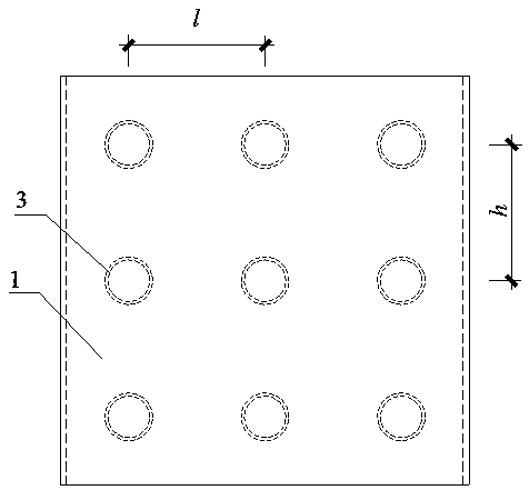
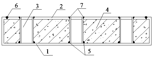
[0021] A circular tube support steel silo, consisting of a steel plate 1, a steel plate 2, and a circular tube support 3 as a basic unit, the two sides of the basic unit are respectively a steel plate 1 and a steel plate 2, wherein the cross section of the steel plate 1 is a curling groove shape, two pieces The thickness t of the steel plate is 2 mm to 3 mm, and the circular tube support 3 is connected to the steel plate 1 through the weld 5. The diameter of the circular tube support 3 is 30 mm to 50 mm, and the thickness is 3 mm. The horizontal and vertical distances between the adjacent circular tube supports 3 are equal. (200-300) t, a circular hole is left at the position corresponding to the steel plate 2 and the circular tube support 3; The steel plates 2 are connected by welds 7; concrete 4 is poured in the empty warehouse formed by the steel plates 1 and 2.

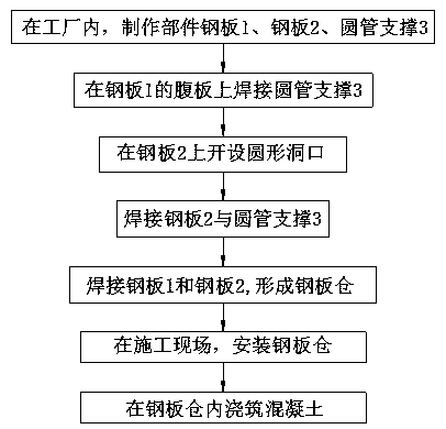
[0022] The manufacture of a steel silo supported by a circular tube includes the following steps:

[0023] (1)...


PUM


Abstract

The invention belongs to the field of shear wall structures, and relates to a circular tube support steel plate silo and a manufacture method thereof. A basic unit is composed of a steel plate 1 and asteel plate 2, and two sides of the basic unit are the steel plate 1 and the steel plate 2; and the middle of the two steel plates are welded with circular tube supports 3, the steel plate 1 and thesteel plate 2 form a steel plate silo, and concrete is poured into the steel plate silo. The manufacture method of the circular tube support steel plate silo comprises the steps that in a factory, thesteel plate 1 is bent to a groove shape with roll rims, and the circular tube supports 3 are welded on the steel plate 1; a circular hole is formed in the steel plate 2; the steel plate 1 and the steel plate 2 are welded; and at the construction site, the concrete is poured into the steel plate silo formed by the steel plate 1 and the steel plate 2. The circular tube supports are welded on the middle of the two steel plates, so that the rigidity outside steel plate planes is increased; a penetrating hollow silo is formed by the two steel plates and the circular tube supports, so that the compactness of the concrete is easy to ensure; and the large-scale steel plate silo can be formed by the basic unit, so that steel can be saved, the welding quantity can be reduced and the splicing efficiency can be improved.

Description

technical field [0001] The invention relates to a shear wall, which belongs to the technical field of construction engineering, in particular to a circular tube-supported steel silo and a manufacturing method thereof. Background technique [0002] Prefabricated building is a structural form of standardized design of building components, factory processing, and on-site assembly. It can reduce environmental pollution caused by construction, shorten the construction period, and save manpower and material resources. The development of housing industrialization, integration, and assembly is the inevitable development direction for China to realize housing innovation and development, structural transformation, and green environmental protection, and the assembly of residential buildings is the basis for realizing the development of residential building industrialization. At present, the country is vigorously encouraging the development of Prefabricated construction industry. [0...

Claims


Application Information

Patent Timeline
Patent Type & Authority Applications(China)
IPC IPC(8): E04C2/28
Inventor 郁有升于德湖王燕
Owner QINGDAO TECHNOLOGICAL UNIVERSITY
Learn More