Vehicle tail gas treatment treating fluid mixing device

A tail gas treatment and mixing device technology, which is applied in the direction of exhaust treatment, exhaust devices, silencers, etc., can solve the problems of affecting tail gas treatment, short mixing path of ammonia gas and tail gas, and insufficient mixing, so as to increase the mixing effect, The effect of simple structure and compact design

Active Publication Date: 2018-06-12
WUXI WEIFU LIDA CATALYTIC CONVERTER
View PDF6 Cites 4 Cited by
  • Summary
  • Abstract
  • Description
  • Claims
  • Application Information

AI Technical Summary

Problems solved by technology

[0003] The purpose of the present invention is to solve the problem that the mixing path of ammonia gas and tail gas is relatively short in the existing SCR process of treating tail gas, and the insufficient mixing affects the treatment of tail gas. It provides a simple structure and compact design that can increase the mixing path of ammonia gas and tail gas. Treatment liquid mixing device for vehicle exhaust gas treatment

Method used


Image

  • Vehicle tail gas treatment treating fluid mixing device
  • Vehicle tail gas treatment treating fluid mixing device
  • Vehicle tail gas treatment treating fluid mixing device

Examples


Embodiment Construction

[0019] The present invention will be further described below in conjunction with specific drawings and embodiments.

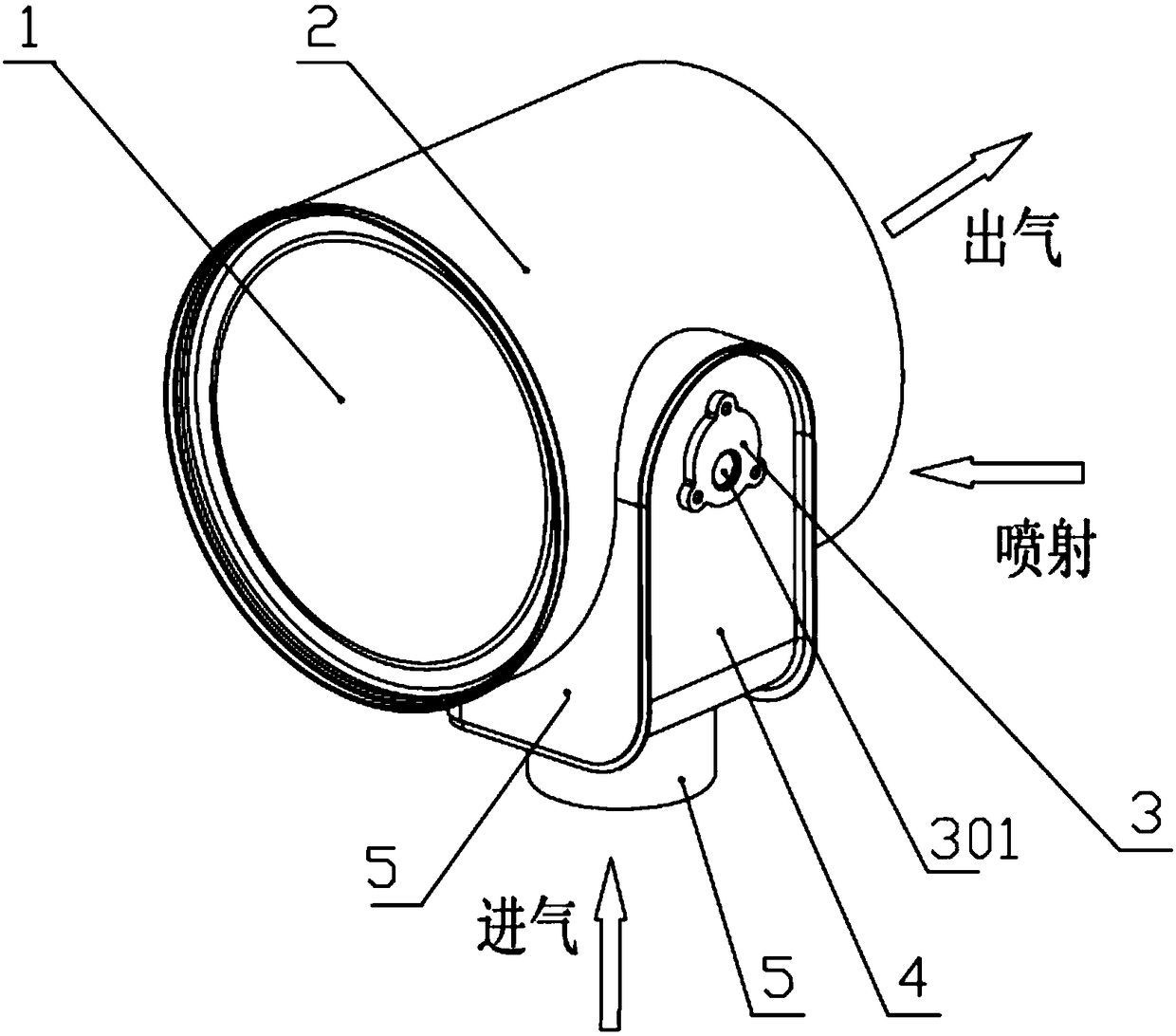
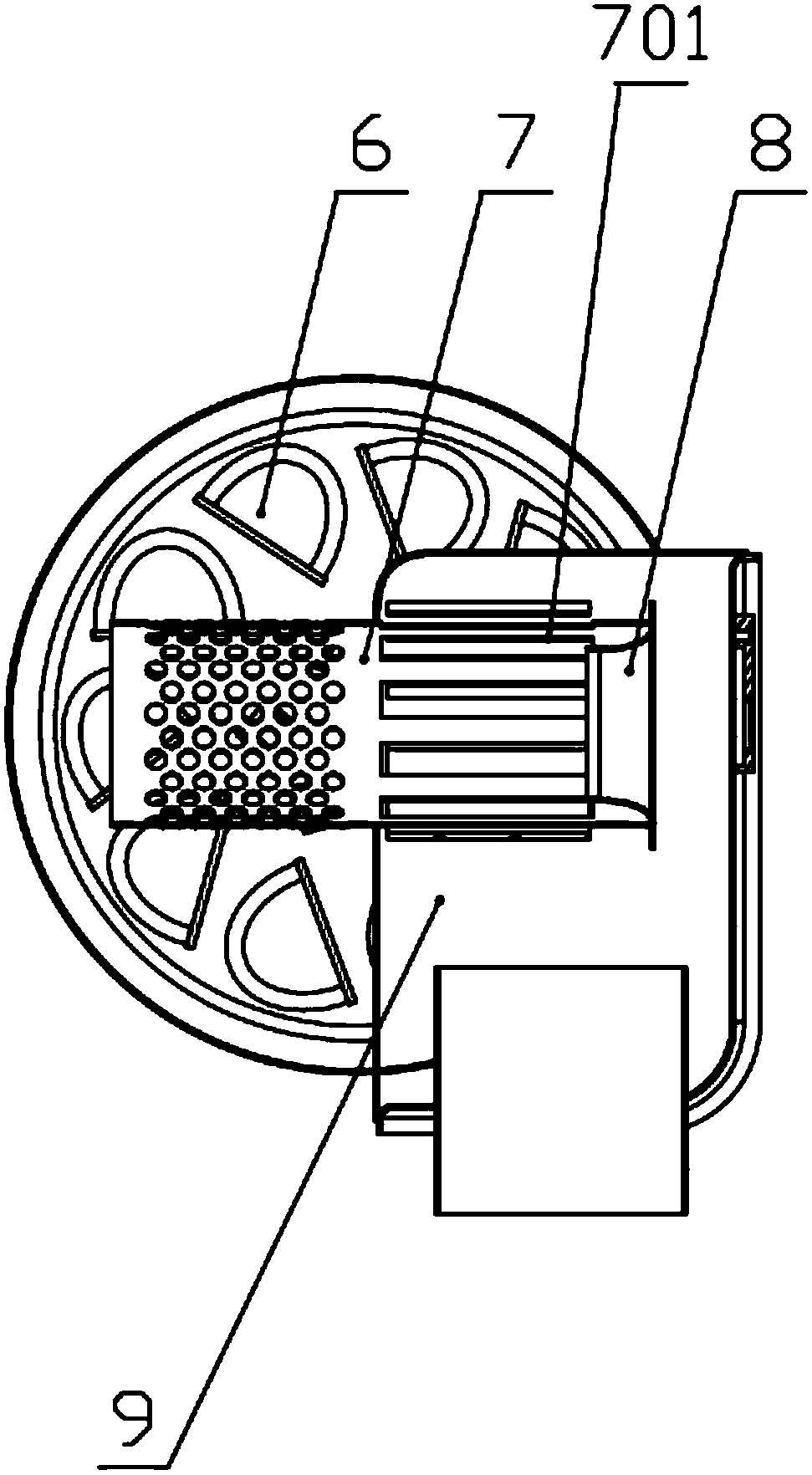
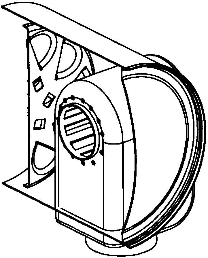
[0020] Such as figure 1 As shown, the vehicle exhaust gas treatment treatment liquid mixing device provided by the present invention includes: a circular end cover 1, a circular cylinder body 2, a urea nozzle mounting seat 3, a U-shaped cavity end cover 4, an air intake pipe 5, a spoiler Separator 6, swirl tube 7, deflector 8, U-shaped cylinder 9;

[0021] The U-shaped cavity end cover 4 is connected with the U-shaped cylinder 9 to form a U-shaped cavity; the circular cylinder 2 is connected with the circular end cover 1 to form a cylindrical cavity, and the U-shaped cavity is embedded in the cylindrical cavity and is located in the cylindrical cavity. The cavity is biased towards the side of the closed end; one end of the cylindrical cavity is closed, and the other end is opened as an air outlet;

[0022] The U-shaped cavity is provided with an inlet pipe 5 ...


PUM


Abstract

The invention provides a vehicle tail gas treatment treating fluid mixing device. The vehicle tail gas treatment treating fluid mixing device is mainly characterized by comprising a first cavity, anda second cavity is formed in the side face of the first cavity; one end of the first cavity is closed, and an opening in the other end of the first cavity serves as a gas outlet; the second cavity isprovided with a gas inlet pipe and a treating fluid inlet; the second cavity is internally provided with a rotational flow pipe aligned with the treating fluid inlet; the rotational flow pipe is provided with vortex generation blades around the axis; the vortex generation blades are located on the section, close to the treating fluid inlet, of the rotational flow pipe, and the other section, deviating from the treating fluid inlet, of the rotational flow pipe is a porous section; the porous section on the rotational flow pipe partially stretches into the first cavity; and turbulent flow partition plates are arranged in the first cavity and behind the second cavity. By means of the vehicle tail gas treatment treating fluid mixing device, the ammonia mist mixing effect can be improved, and ammonia gas and tail gas are mixed more sufficiently.

Description

technical field [0001] The invention relates to a urea mixing device for vehicle tail gas treatment, belonging to the technical field of diesel engine tail gas treatment system equipment. Background technique [0002] As diesel engine emission regulations become increasingly stringent, exhaust gas after-treatment technology is a technical measure that must be adopted. However, SCR can meet the national IV, V and national VI emission standards. The basic principle of SCR is to atomize 32.5% aqueous urea solution through the urea injection system (commonly known as urea pump) and spray it into the exhaust pipe to mix with the engine exhaust. The aqueous solution undergoes pyrolysis and hydrolysis reactions to generate ammonia gas (NH 3 ), under the action of the catalyst, ammonia converts harmful nitrogen oxides (NOx) in diesel engine exhaust into harmless nitrogen (N 2 ) and water, the primary task of the SCR route of engine exhaust gas treatment technology is to effectivel...

Claims


Application Information

Patent Timeline
Patent Type & Authority Applications(China)
IPC IPC(8): F01N3/28F01N3/20
CPCF01N3/2066F01N3/2892F01N2610/02F01N2610/08Y02A50/20
Inventor 曲洪亮段一军朱亮吴杰惠志君林浩健徐超郭一博徐文清
Owner WUXI WEIFU LIDA CATALYTIC CONVERTER
Why Eureka
Try Eureka