
Fuse salt phase-change heat storage electric boiler

A phase-change heat storage and electric boiler technology, applied in heat storage heaters, fluid heaters, indirect heat exchangers, etc., can solve the problems of small heat storage, high safety performance requirements, low heat storage temperature, etc., to prevent Heat reflux, good heat transfer performance, and high heat storage density

Inactive Publication Date: 2018-06-12
SOUTHEAST UNIV
View PDF5 Cites 21 Cited by
  • Summary
  • Abstract
  • Description
  • Claims
  • Application Information

AI Technical Summary

Problems solved by technology

The existing water thermal storage electric boiler has the following problems: The heat storage temperature is low (only 90°C), thus limiting the range of heat utilization, it can only be used for low-temperature heat exchange and heating, and cannot be used for power generation; The pressure of the equipment is high, high-pressure pressure-bearing equipment is required, and the safety performance requirements are high; It belongs to sensible heat storage, with small heat storage capacity and large equipment footprint
The existing molten salt heat storage equipment only uses the sensible heat of molten salt to store heat, and the heat storage is small. The heat exchanger is mostly of plate or shell and tube type, and its thermal conductivity is relatively poor. It does not have the functions of thermal diodes and thermal switches. heat exothermic heat release unstable

Method used


Image

  • Fuse salt phase-change heat storage electric boiler

Examples


Embodiment Construction

[0022] The present invention will be further illustrated below in conjunction with specific embodiments, and it should be understood that the following specific embodiments are only used to illustrate the present invention and are not intended to limit the scope of the present invention.

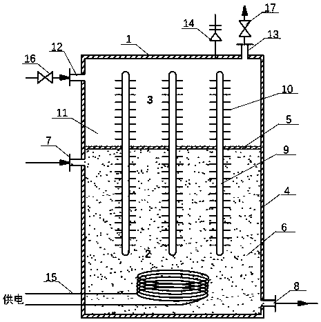
[0023] figure 1 It is a structural schematic diagram of the present invention, such as figure 1 As shown, the molten salt phase change heat storage electric boiler of the present invention includes a boiler tank body 1, and the inside of the boiler tank body is divided into a heat transfer chamber 3 and a heat storage chamber 2 by a partition plate 5, and the inside of the heat storage chamber A heat storage medium 6 is provided, a heat transfer medium 11 is provided in the heat transfer chamber, an immersion electric heater 15 is provided in the heat storage chamber, and the heat storage chamber is respectively connected to the heat storage medium inlet 7 and the heat storage medium outlet...


PUM


Abstract

The invention discloses a fuse salt phase-change heat storage electric boiler. The fuse salt phase-change heat storage electric boiler comprises a boiler tank body, the interior of the boiler tank body is portioned into a heat transferring cavity and a heat storage cavity through a partition plate, and a heat storage medium is arranged in the heat storage cavity. A heat transferring medium is arranged in the heat transferring cavity, an immersed-type electric heater is arranged in the heat storage cavity, and the heat storage cavity is connected with a heat storage medium inlet and a heat storage medium outlet. The heat transferring cavity is connected with a heat transferring medium inlet and a heat transferring medium outlet, and a set of heat tubes penetrating through the partition plate are arranged in the boiler tank body. According to the fuse salt phase-change heat storage electric boiler, a heat tube exchanger is adopted, compared with an ordinary exchanger, the heat transferring performance is better, storage heat can be rapidly extracted, and efficient heat transferring is achieved; through the diode characteristic of the heat tubes, heat one-way transferring is ensured,and heat back flowing is prevented; and through the heat switch characteristic of the heat tubes, the work temperature range of the heat storage medium is controlled, it is ensured that solid-liquid phase-change circulation occurs near fused points, and the phase-change energy storage characteristic of fuse salt is maintained.

Description

Technical field: [0001] The invention relates to a molten salt phase change heat storage electric boiler, which belongs to the technical field of heat storage and heat storage. Background technique: [0002] In order to actively promote the prevention and control of air pollution, my country's clean and renewable energy power generation has grown rapidly, and the installed capacity of wind power and photovoltaic power generation has been greatly improved. However, wind power and photovoltaic power generation have intermittent, random, low dispatchability and obvious gaps. Problems such as the reverse peak-shaving characteristics make the grid-connection, peak-shaving and consumption of new energy become the bottleneck of its development, resulting in low utilization efficiency of wind power and photovoltaics, and the phenomenon of "abandoning wind and solar" is prominent. [0003] Heat storage technology utilizes unstable wind power, photovoltaics, and night-time trough elect...

Claims


Application Information

Patent Timeline
IPC IPC(8): F22B1/06F22B1/28F24H7/02F24H9/18F28D15/00
CPCF22B1/06F22B1/28F24H7/0233F24H9/1818F28D15/025
Inventor 蔡亮陈丽萍张小松陈涛李光华
Owner SOUTHEAST UNIV
Learn More