
One-time well completion method through VCR method

A one-off, high-well technology, applied in blasting and other directions, can solve problems such as the inability to form the center of the pilot tunnel, the inability to complete the blasting of the wellbore, and the blockage of the middle and upper blasting, and achieve high explosive utilization, good well-forming effect, and high-efficiency well-forming

Inactive Publication Date: 2018-06-12
TIBET HUATAILONG MINING DEV
View PDF1 Cites 6 Cited by
  • Summary
  • Abstract
  • Description
  • Claims
  • Application Information

AI Technical Summary

Problems solved by technology

This patent first uses the VCR method to drill blasting blastholes, utilizes the free surface of the lower space and the compensation space of the surrounding holes to quickly form the central pilot tunnel of the patio, and then uses the blastholes outside the central pilot tunnel to implement lateral blasting once to complete the well; but in the actual well completion In the process, this kind of processing method still has the following defects: 1. This patent is to blast the cutting center successively at first. Since the free surface of the blasting cutting center only has the compensation hole and the narrow central guide tunnel below, it is successively blasting and digging from bottom to top. When the center of the groove is cut, the cross section of the center of the cut will become smaller and smaller, and the blast will be more difficult. This is due to the accumulation of errors in the center of each cut and blast, resulting in the highest well completion height of this patent can only reach 30m
2. When blasting the cutting center successively from the bottom to the top, due to the accumulation of errors in each blasting, the section of the cutting center becomes smaller and smaller, and it is very easy to cause blasting blockage in the middle and upper parts, and the entire guide tunnel center cannot be formed, and thus cannot be completed. blasting the entire wellbore

Method used


Image

  • One-time well completion method through VCR method
  • One-time well completion method through VCR method
  • One-time well completion method through VCR method

Examples


Embodiment 1

[0027] This embodiment discloses a one-time well forming method of the VCR method, comprising the following steps:

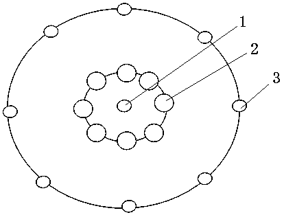
[0028] a. Drill a center hole 1 at the center of the raised well face of the proposed well, and then drill a compensation hole 2 around the center hole 1 and a peripheral hole 3 around the center hole 1 in sequence. The compensation hole 2 and the peripheral hole 3 are both in line with the center Hole 1 is vertically parallel (eg figure 1 shown).

[0029] In this step, preferably, the diameters of the central hole 1 and the peripheral hole 3 are both 80 mm, and the diameter of the compensation hole 2 is 120 mm. The distance between the peripheral hole 3 and the central hole 1 is 800mm, the distance between any two adjacent peripheral holes 3 is 1500mm, and the distance between the compensation hole 2 and the central hole 1 is 300mm.

[0030] In this step, the central hole 1, the compensation hole 2 and the peripheral hole 3 are all drilled and formed at one t...

Embodiment 2

[0040] This embodiment discloses a one-time well forming method of the VCR method, comprising the following steps:

[0041] a. Drill a center hole 1 at the center of the raised well face of the proposed well, and then drill a compensation hole 2 around the center hole 1 and a peripheral hole 3 around the center hole 1 in sequence. The compensation hole 2 and the peripheral hole 3 are both in line with the center Hole 1 is vertically parallel (eg figure 1 shown).

[0042]In this step, preferably, the diameters of the central hole 1 and the peripheral hole 3 are both 100 mm, and the diameter of the compensation hole 2 is 150 mm. The distance between the peripheral hole 3 and the central hole 1 is 1200mm, the distance between any two adjacent peripheral holes 3 is 1800mm, and the distance between the compensation hole 2 and the central hole 1 is 3500mm.

[0043] b. The central hole 1 and the peripheral hole 3 are charged with explosives in sections, and two adjacent sections of...

Embodiment 3

[0046] This embodiment discloses a one-time well forming method of the VCR method, comprising the following steps:

[0047] a. Drill a center hole 1 at the center of the raised well face of the proposed well, and then drill a compensation hole 2 around the center hole 1 and a peripheral hole 3 around the center hole 1 in sequence. The compensation hole 2 and the peripheral hole 3 are both in line with the center Hole 1 is vertically parallel (eg figure 1 shown).

[0048] In this step, preferably, the diameters of the central hole 1 and the peripheral hole 3 are both 90 mm, and the diameter of the compensation hole 2 is 130 mm. The distance between the peripheral hole 3 and the central hole 1 is 1000mm, the distance between any two adjacent peripheral holes 3 is 1650mm, and the distance between the compensation hole 2 and the central hole 1 is 400mm.

[0049] b. The central hole 1 and the peripheral hole 3 are charged with explosives in sections, and two adjacent sections of ...


PUM


Abstract

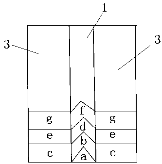
The invention discloses a one-time well completion method through a VCR method. The one-time well completion method comprises the following steps that a, a center hole is drilled in the center of a working face of a raise where a well is proposed to be completed, and then compensating holes and periphery holes surrounding the center hole are sequentially drilled by taking the center hole as a center; b, the center hole and the periphery holes are internally filled with explosives in a deck charge mode, and every two adjacent sections of explosives in the same hole are separated by a bulkhead;and c, the center hole is blasted firstly to expand a groove cavity, then a millisecond blasting method is utilized to conduct sectional blasting in the blasting sequence of the center hole first andthen the periphery holes, and tower blasting is formed till the whole raise is completely blasted. According to the one-time well completion method through the VCR method, one-time well completion canbe achieved by adopting the tower blasting mode, and the one-time well completion method has the advantages that the well completion effect is good and the well completion efficiency is high.

Description

technical field [0001] The invention relates to the technical field of beneficiation production, in particular to a one-time well-forming method by the VCR method. Background technique [0002] A raised shaft is a vertical or inclined shaft that connects two or more stages as a way to slide ore rock. In mining, because most of the mines are very high and the ore is transported frequently, in order to improve the transport efficiency and save costs, a pipeline similar to a well will be opened from top to bottom in some mines, and the ore will be dumped directly from top to bottom, and the transport vehicles will wait in the underground. Go, ship directly. On the one hand, the patio can improve the transportation efficiency. On the other hand, because it is directly dumped vertically, the use of height can play a certain role in crushing ore. [0003] The prior art with the Chinese patent notification number CN106089212 disclosed a hard rock rapid excavation raising blasting...

Claims


Application Information

Patent Timeline
Patent Type & Authority Applications(China)
IPC IPC(8): F42D1/00F42D3/04
CPCF42D1/00F42D3/04
Inventor 关士良王平陈国良赵海洋曹俊肖晓肖满琳王长丕乔德元
Owner TIBET HUATAILONG MINING DEV
Learn More