
A mobile power soldering machine

A mobile power supply, soldering machine technology, applied in welding equipment, tin feeding device, welding/welding/cutting items, etc., can solve the problems of easy deviation, inaccurate solder positioning, and inability to realize full automation, so as to simplify manual operation , Improve production efficiency, improve work efficiency

Active Publication Date: 2020-06-16
湖南双智科技有限公司
View PDF6 Cites 0 Cited by
  • Summary
  • Abstract
  • Description
  • Claims
  • Application Information

AI Technical Summary

Problems solved by technology

The soldering operation of the existing soldering machine is mainly done manually, the efficiency of manual soldering is low, the size of the solder point is uneven, the soldering position is not accurate, it is easy to deviate, the soldering is not firm, the product yield is low, and the labor cost is high, resulting in high production costs.
However, the existing automatic soldering machine is difficult to ensure all-round work during soldering, and there will be no dead angles causing quality problems
Because there are various electronic components of different heights on the existing products, if the soldering iron is soldered at a vertical angle, it is easy to burn the electronic components next to it, and the quality of the product cannot be guaranteed. It is necessary to separate the steps and use manual soldering. In this way, the requirement of full automation cannot be realized.

Method used


Image

  • A mobile power soldering machine
  • A mobile power soldering machine
  • A mobile power soldering machine

Examples


Embodiment Construction

[0059] The present invention will be further explained below in conjunction with the accompanying drawings and specific embodiments. It should be understood that the following specific embodiments are only used to illustrate the present invention and are not intended to limit the scope of the present invention.

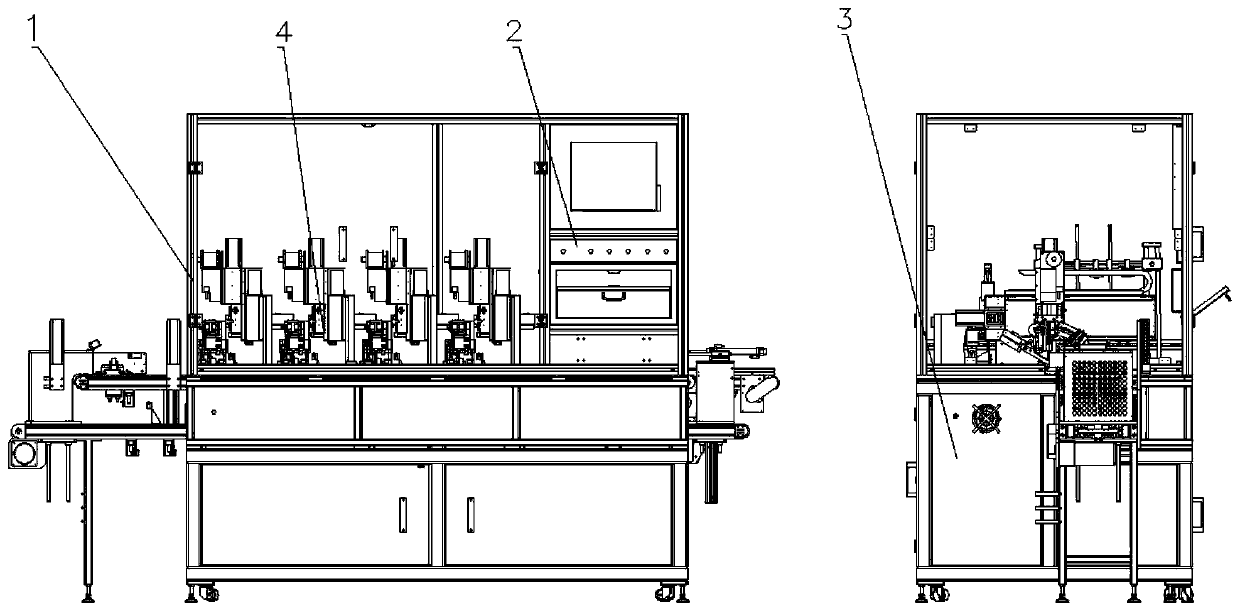
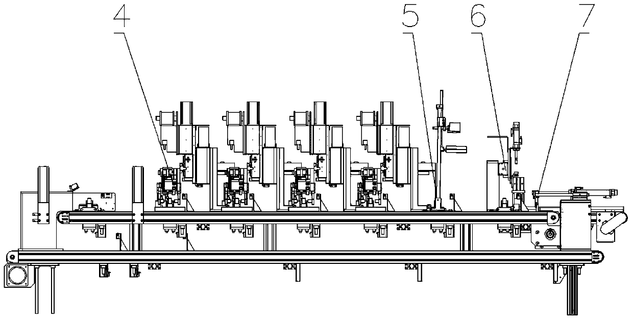
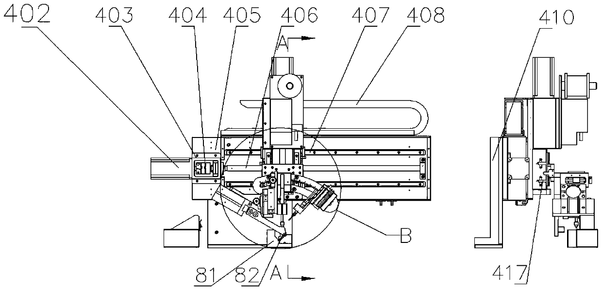
[0060] Such as figure 1 , 2 As shown, a mobile power supply soldering machine includes a frame 1, a control panel 2, an electrical cabinet 3, a welding mechanism 4, a CCD detection mechanism 5, a retrieving mechanism 6 and a return conveying mechanism 7, and the upper end surface of the electrical cabinet 3 A frame 1 is installed, and the frame is used to support the welding mechanism 4, the CCD detection mechanism 5, the retrieving mechanism 6 and the return conveying mechanism 7, and the conveying direction along the upper conveying line 724 of the return conveying mechanism 7 is sequentially A welding mechanism 4, a CCD detection mechanism 5 and a material retriev...


PUM


Abstract

The invention relates to a mobile power supply soldering machine, and mainly solves the problem that an existing soldering machine is low in production efficiency and a quality of a product is difficult to guarantee can be solved. The mobile power supply soldering machine comprises a rack, a control panel, an electric cabinet, welding mechanisms, a CCD detection mechanism, a material taking mechanism and a backflow conveying mechanism, wherein the upper end surface of the electric cabinet is provided with the rack, the rack is used for supporting the welding mechanisms, the CCD detection mechanism, the material taking mechanism and the backflow conveying mechanism. According to the invention, the welding mechanisms, the CCD detection mechanism, the material taking mechanism are sequentially arranged along the conveying direction of an upper conveying line of the backflow conveying mechanism, the problem is well solved, and the machine can be used as soldering tin of the mobile power supply.

Description

technical field [0001] The invention relates to a mobile power supply soldering machine. Background technique [0002] In the field of electronic product processing, various processing equipment are often used, and soldering machine is one of the more important equipment. The soldering operation of the existing soldering machine is mainly done manually, the efficiency of manual soldering is low, the size of the solder point is uneven, the soldering position is not accurate, it is easy to deviate, the soldering is not firm, the product yield is low, and the labor cost is high, resulting in high production costs. . However, it is difficult for the existing automatic soldering machine to ensure all-round work during soldering, and there will be no dead angles to cause quality problems. Because there are various electronic components of different heights on the existing products, if the soldering iron is soldered at a vertical angle, it is easy to burn the electronic component...

Claims


Application Information

Patent Timeline
Patent Type & Authority Patents(China)
IPC IPC(8): B23K1/00B23K3/03B23K3/06B23K3/08B23K101/36
CPCB23K1/0008B23K3/03B23K3/063B23K3/08B23K3/087
Inventor 郭龙吉
Owner 湖南双智科技有限公司
Learn More