
Laser scanning grinding system and method

A laser scanning and laser signal technology, which is applied in the direction of grinding machines, grinding workpiece brackets, grinding machine parts, etc., can solve the problems of not being able to perform targeted grinding on casting defects, not allowing comprehensive grinding, automatic identification and grinding, etc. , to achieve the effect of reducing grinding workload, shortening grinding time, improving precision and safety

Active Publication Date: 2018-06-15
鹰普航空科技有限公司
View PDF11 Cites 3 Cited by
  • Summary
  • Abstract
  • Description
  • Claims
  • Application Information

AI Technical Summary

Problems solved by technology

However, this mode of grinding system uses parts movement to fit the position of the abrasive belt, and can only be used for overall grinding and polishing of the surface of simple and undifferentiated parts. The key is when the casting parts have complex structures and cannot be fully polished. It is not possible to accurately identify and polish the abnormal parts automatically
The robot grinding device discloses a device that replaces the traditional manual grinding. During the grinding process, it can avoid protrusions or obstacles without damaging the grinding headgear, but it does not solve the problem of automatic identification of the parts that need grinding.
An industrial robot grinding and polishing workstation based on offline programming discloses that offline programming can be used to solve the problem of non-targeted grinding trajectory. The abnormal position is random, there is no rule to find and it is powerless to polish the non-abnormal parts

Method used


Image

  • Laser scanning grinding system and method
  • Laser scanning grinding system and method
  • Laser scanning grinding system and method

Examples


Embodiment Construction

[0036] Specific embodiments of the present invention will be described in detail below in conjunction with the accompanying drawings. It should be understood that the specific embodiments described here are only used to illustrate and explain the present invention, and are not intended to limit the present invention.

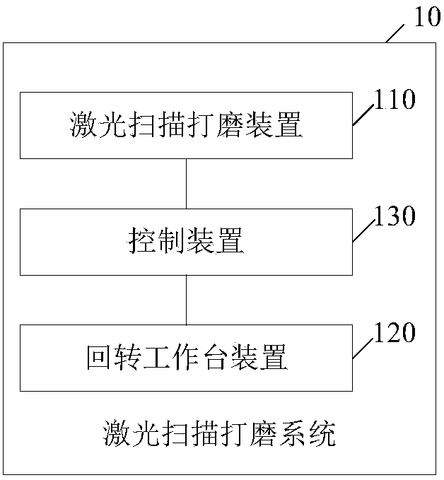
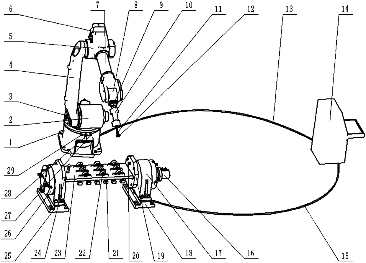
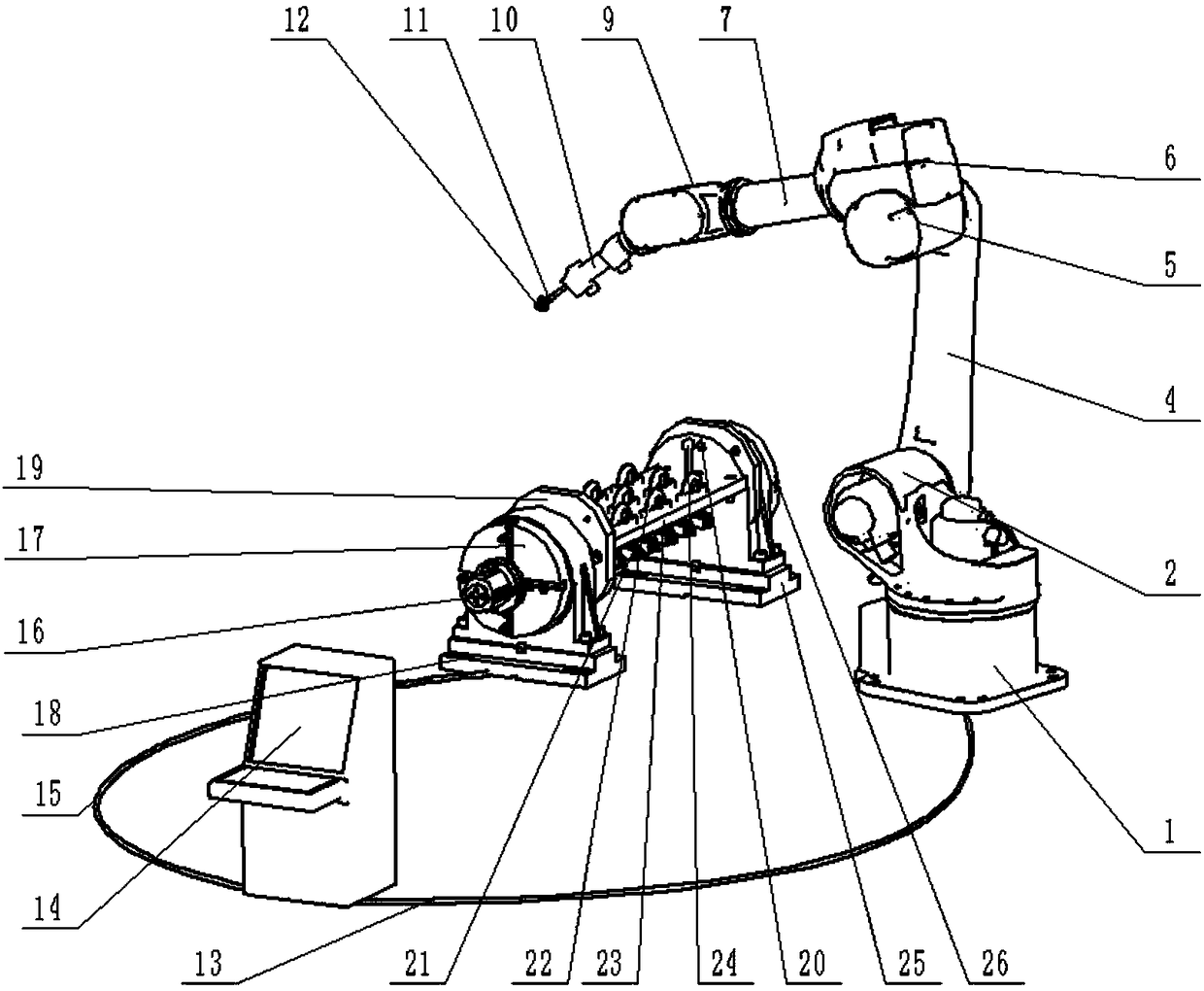
[0037] As a first aspect of the present invention, a laser scanning grinding system is provided, wherein, as figure 1 and figure 2 As shown, the laser scanning grinding system 10 includes: a laser scanning grinding device 110, a rotary table device 120 and a control device 130, and the laser scanning grinding device 110 and the rotary table device 120 are connected with the control device 130 connected, the laser scanning grinding device 110 and the rotary table device 120 are arranged adjacently,

[0038] The laser scanning grinding device 110 includes a robot rotary base 1 and a grinding mechanism arranged on the robot rotary base 1, and the robot rotary ba...


PUM


Abstract

The invention relates to the technical field of grinding and polishing, and particularly discloses a laser scanning grinding system. The laser scanning grinding system comprises a laser scanning grinding device, a rotary workbench device and a control device. The laser scanning grinding device and the rotary workbench device are both connected with the control device. The laser scanning grinding device comprises a robot rotary base and a grinding mechanism arranged on the robot rotary base. A first laser scanning transmitting device, a second laser scanning transmitting device and a laser receiving device are arranged on the side, facing the rotary workbench device, of the robot rotary base. The laser receiving device is located between the first laser scanning transmitting device and thesecond laser scanning transmitting device. The rotary workbench device comprises a rotary workbench. The rotary workbench is used for fixing multiple to-be-ground parts and is provided with a third laser scanning transmitting device. The invention further discloses a laser scanning grinding method. The laser scanning grinding system has the advantage of precise grinding.

Description

technical field [0001] The invention relates to the technical field of grinding and polishing, in particular to a laser scanning grinding system and a laser scanning grinding method. Background technique [0002] Casting grinding and polishing methods mainly include manual grinding and machine grinding. At present, most castings still rely on manual grinding and polishing. Manual grinding has low efficiency, high labor intensity, and serious pollution. The dust produced is very harmful to workers. To meet the production needs. In addition, due to the different proficiency of workers, the product consistency is poor and the scrap rate is high. With the increase in human resource costs and the reduction of labor resources, the casting industry urgently needs to use automated equipment to replace manual operations, but the machine grinding process When encountering protrusions or obstacles in the process, the grinding head will be damaged. The biggest problem is that the curr...

Claims


Application Information

Patent Timeline
Patent Type & Authority Applications(China)
IPC IPC(8): B24B19/00B24B51/00B24B49/12B24B41/06B25J11/00
CPCB24B19/00B24B41/06B24B49/12B24B51/00B25J11/0065
Inventor 马鸿杰马毅青朱力微贾波朱晨麓王澜睿
Owner 鹰普航空科技有限公司
Learn More