Device and method for testing condensate water formation

A test method and condensate technology, applied in the direction of measuring devices, material condensation, instruments, etc., can solve the problem of large temperature differences, wide ranges of atmospheric temperature and humidity changes, and inability to meet the requirements of material and mechanical product application verification and service reliability evaluation To achieve the effect of improving system reliability, mature technology, and reasonable data parameters

Active Publication Date: 2018-06-19
CHINA ACADEMY OF SPACE TECHNOLOGY
View PDF10 Cites 5 Cited by
  • Summary
  • Abstract
  • Description
  • Claims
  • Application Information

AI Technical Summary

Problems solved by technology

However, the airtight cabin of the crew cabin of the space station has variable pressure (with low pressure conditions), the cabin is a mixed gas atmosphere, the atmosphere temperature and humidity vary widely, and the temperature differences of various materials and products are large. The ability to produce condensed water on the surface of materials or product

Method used


Image

  • Device and method for testing condensate water formation
  • Device and method for testing condensate water formation
  • Device and method for testing condensate water formation

Examples


Embodiment 1

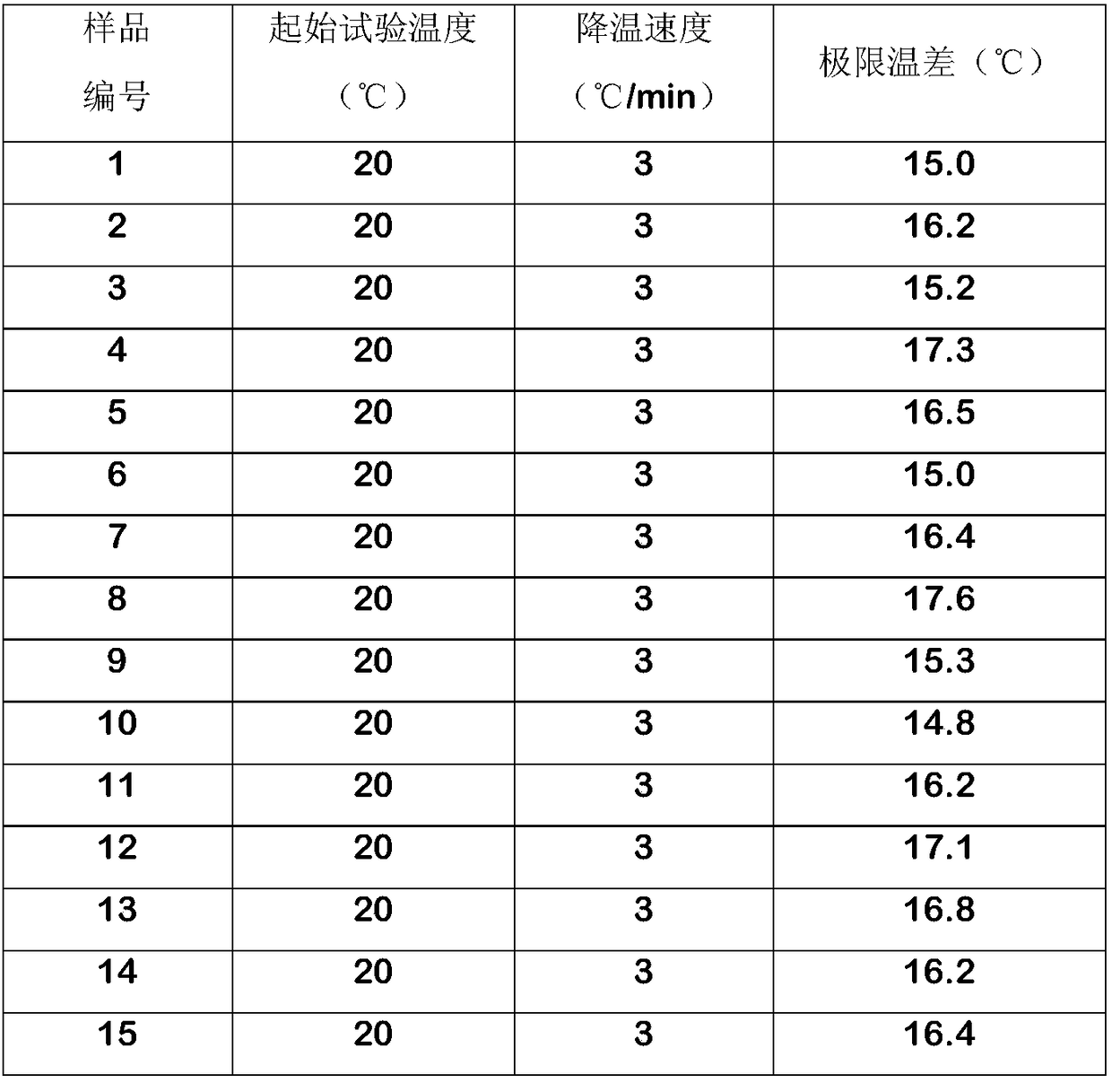
[0054] Embodiment 1 (measurement of limit temperature difference)

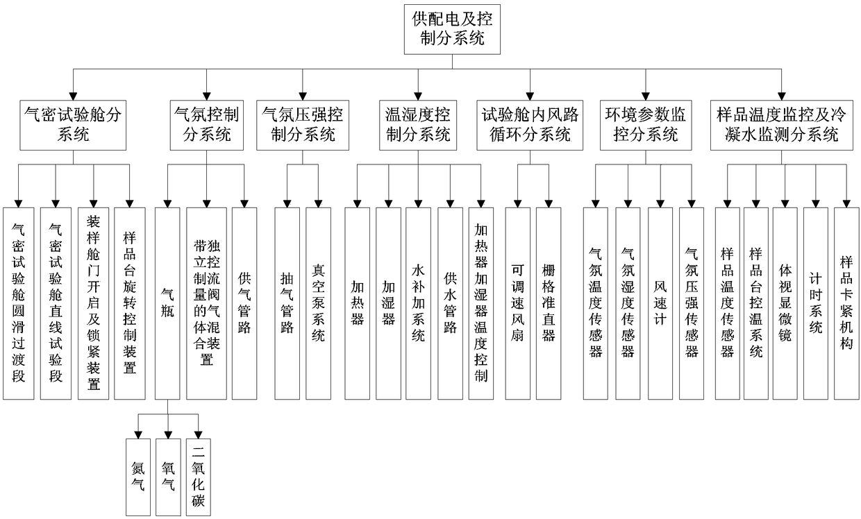
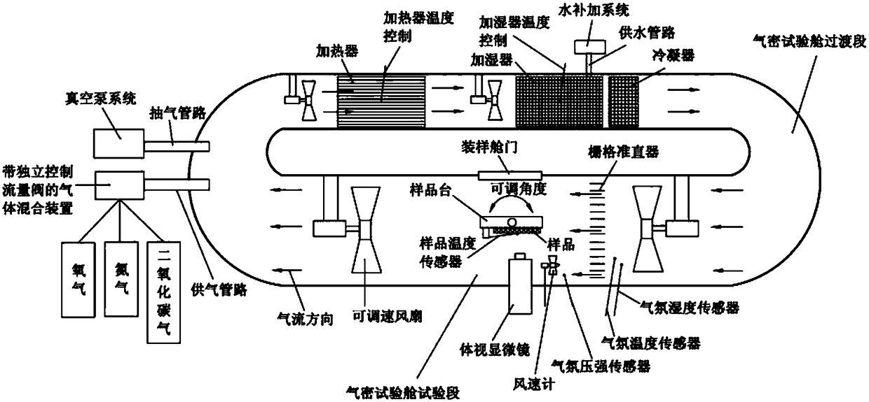
[0055] A test device for forming condensed water, the device includes an atmosphere control subsystem, an atmosphere pressure control subsystem, a temperature and humidity control subsystem, an airtight test cabin subsystem, an air circuit circulation subsystem in the test cabin, and an environmental parameter monitoring subsystem , Sample temperature monitoring and condensate monitoring subsystem, power supply and distribution and control subsystem;

[0056] The atmosphere control subsystem includes a gas mixing device with an independently controlled flow valve, an oxygen cylinder, a nitrogen cylinder, a carbon dioxide gas cylinder and a gas supply pipeline, and the gas mixing device with an independently controlled flow valve includes a pressure reducing valve, a flow meter And four-way (three in and one out), oxygen cylinders, nitrogen cylinders, and carbon dioxide cylinders are equipped with a pressure re...

Embodiment 2

[0104] Embodiment 2 (product verification test)

[0105] (1) Pretreatment of the sample to be tested, that is, the circuit board sample with an outer contour size of 40mm×50mm×10mm (thickness) is blown off the dust attached to the surface with an ear cleaning ball, and then placed in a desiccator for standby.

[0106] (2) The laboratory environment is 22° C., 45% RH, and 0.9 atm as measured by a thermo-hygrometer.

[0107] (3) Initialize the test device, set the initial environmental conditions (temperature, humidity, pressure) parameters through the power supply and distribution and control subsystems: atmosphere 22°C, 30% RH, 0.9atm, sample stage 32°C, and run the system using The heater, humidifier, and condenser of the temperature and humidity control system and the temperature control system of the sample stage rotation control device are started. Adjust the gas cylinder pressure reducing valve and flow valve of the atmosphere control subsystem to obtain 0.9 atm gas with...


PUM


Abstract

The invention relates to a device and a method for testing condensate water formation. The device is used for testing the minimum difference value of surface temperature of a tested sample and given gas temperature when condensate water is formed on the surface of the tested sample by gradually reducing temperature of the tested sample in the given atmosphere environment (atmosphere includes gas temperature, humidity, components and pressure intensity), and the device is further used for testing the maximum duration of keeping condensate-water-free state on the surface of the tested sample under the circumstance that temperature of the surface of the tested sample and the given atmosphere conditions are determined. The invention particularly relates to application verification of a material and a mechanical product and service reliability evaluation, in particular to the method for measuring limit temperature difference when the condensate water is formed on bare surface due to temperature difference between the material or the product and the experiment environment in the simulation test environment with controllable temperature, humidity, atmosphere and pressure intensity or evaluating service reliability of the material or the product and the testing device.

Description

technical field [0001] The invention relates to a device and method for testing the formation of condensed water. The device is used for testing in a given atmosphere (the atmosphere includes the temperature, humidity, composition and pressure of the gas), by gradually reducing the temperature of the sample to be tested. Temperature, when detecting the formation of condensed water on the surface of the tested sample, the minimum difference between the temperature of the measured sample surface and the given gas temperature, and when the temperature of the tested sample surface and the given atmospheric conditions are determined, is determined The longest time for measuring the surface of the sample to maintain a non-condensing water state; specifically involves the application verification and service reliability evaluation of materials and mechanical products, specifically a material or product in a simulated test environment with controllable temperature, humidity, atmosphere...

Claims


Application Information

Patent Timeline
IPC IPC(8): G01N25/14
CPCG01N25/142
Inventor 于翔天秦怀德汪洋吴冰何端鹏李旭然李岩王向轲高鸿邢焰
Owner CHINA ACADEMY OF SPACE TECHNOLOGY
Why Eureka
Try Eureka