
Decoupled semi-linearization optimal power flow model based on warm start environment

An optimal power flow and linearization technology, applied in the field of power systems, can solve the problems that the calculation efficiency of the AC optimal power flow model is difficult to meet the needs of large power grid operation analysis, lack of fast provision of a good operating environment, and high dependence on the operating environment. Reduce the degree of nonlinearity, expand the scope of application, and solve the effect of high dependence

Active Publication Date: 2018-06-19
HOHAI UNIV
View PDF6 Cites 2 Cited by
  • Summary
  • Abstract
  • Description
  • Claims
  • Application Information

AI Technical Summary

Problems solved by technology

[0005] Purpose of the invention: The calculation efficiency of the AC optimal power flow model is difficult to meet the needs of large power grid operation analysis, the DCOPF model does not take into account the influence of voltage amplitude and reactive power, and it is impossible to obtain complete dispatch information and hot start linearization models Due to the high dependence on the operating point and the lack of methods to quickly provide a good operating environment, a semi-linear model is proposed that decouples the voltage amplitude and phase angle, and the voltage amplitude is nonlinear but the phase angle is linear.
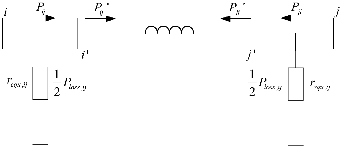
For the phase angle operating point information required for the model to linearize the phase angle, the present invention rationally utilizes the existing high-precision DC optimal power flow model based on the network loss equivalent load, and uses the obtained results as the model described in the present invention. The required phase angle operating point, thus effectively solving the problem of high dependence of the hot start model on the operating environment, and expanding the scope of application of the model

Method used


Image

  • Decoupled semi-linearization optimal power flow model based on warm start environment
  • Decoupled semi-linearization optimal power flow model based on warm start environment
  • Decoupled semi-linearization optimal power flow model based on warm start environment

Examples


Embodiment Construction

[0039] Below in conjunction with specific embodiment, further illustrate the present invention.

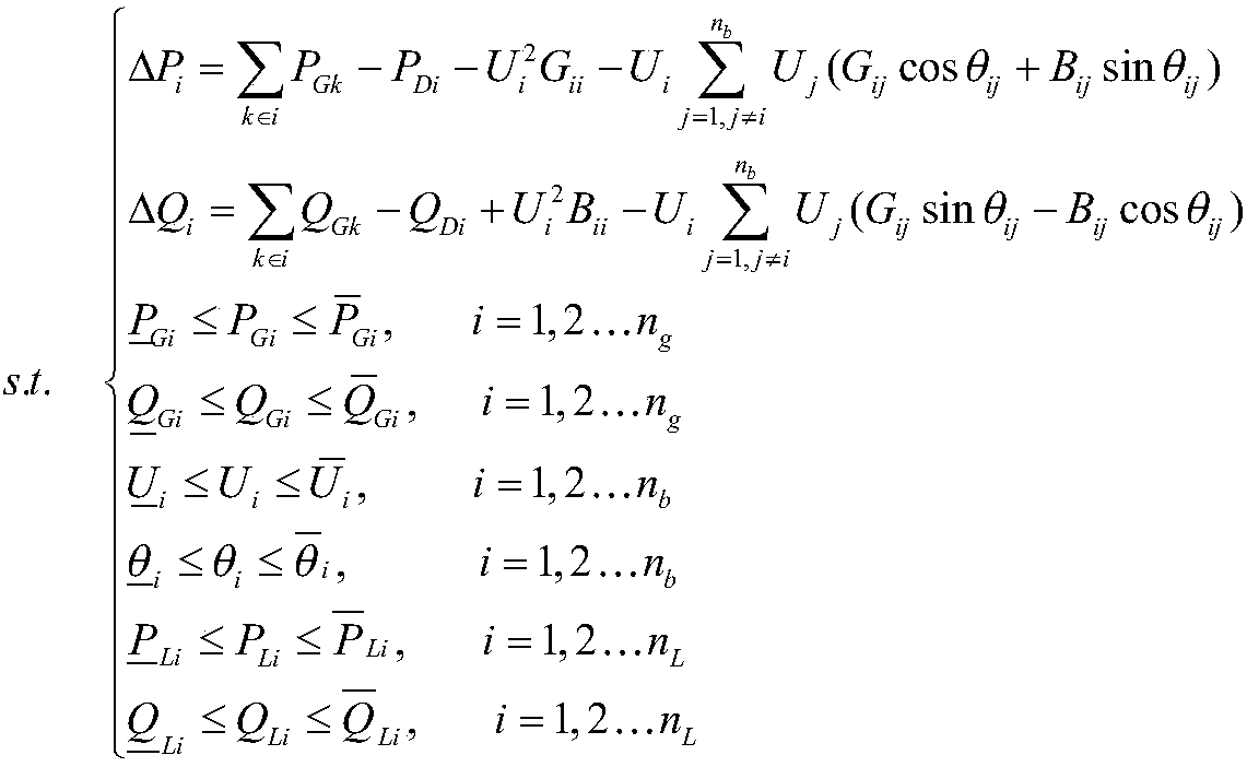
[0040] The idea of ​​the present invention is to start from the AC optimal power flow model, analyze the nonlinear characteristics in the AC optimal power flow model, perform approximate equivalents on the trigonometric function items in the system power balance equation by polynomial fitting, and use the system operation Features Decouple the voltage amplitude and phase angle, and linearize the quadratic term of the phase angle in the decoupled power balance equation through Taylor series expansion, and use the existing high-precision network loss-based equivalent load The results obtained from the DC optimal power flow model are used as the phase angle operating point information required by the present invention, thereby effectively solving the problem of dependence of hot start models on the operating environment.

[0041] AC optimal power flow is a typical nonlinear programming...


PUM


Abstract

The invention discloses a decoupled semi-linearization optimal power flow model based on a warm start environment. The method includes: firstly, performing polynomial fitting on trigonometric functionterms in a power balance equation, and decoupling a voltage amplitude and a phase angle by employing operation characteristics of a system; then performing linearization processing on quadratic termsof the phase angle through the mode of Taylor series expansion; and finally obtaining the semi-linearization optimal power flow model with linear voltage phase angle and non-linear amplitude by regarding a result of a direct current optimal power flow model based on a power loss equivalent load as an operating point of Taylor series expansion of the quadratic terms of the phase angle. According to the semi-linearization optimal power flow model, the problem of dependence on the operating environment by warm start models is well solved, and the calculating precision of the linearization modeland the adaptability to a large system are improved.

Description

technical field [0001] The invention relates to a linearized optimal power flow model of a power system, which belongs to the technical field of power systems. Background technique [0002] Optimal power flow (OPF) calculation was first proposed by French scholar Carpentier in the 1960s, and it is an important means to ensure the safe and economical operation of power systems. However, the alternating current optimal power flow (ACOPF) model has strong nonlinear characteristics, and the coupling between its variables is very tight, which leads to low computational efficiency of the model and cannot meet the online requirements of large-scale systems. real-time computing needs. Therefore, it is particularly important to find a suitable linearized OPF model. Direct current optimal power flow (DCOPF) is currently the fastest linearized OPF model. However, since the model ignores the network loss and does not consider the influence of voltage amplitude and reactive power, its...

Claims


Application Information

Patent Timeline
IPC IPC(8): H02J3/06
CPCH02J3/06H02J2203/20
Inventor 卫志农朱梓荣孙国强臧海祥张清松
Owner HOHAI UNIV
Learn More