
Medical retractor

A retractor and retraction technology, applied in the field of medical supplies, can solve problems such as difficult operation

Inactive Publication Date: 2018-06-22
丁汉君 +1
View PDF8 Cites 2 Cited by
  • Summary
  • Abstract
  • Description
  • Claims
  • Application Information

AI Technical Summary

Problems solved by technology

[0003] Existing retractors usually include two handles and retracting blades, the two handles are hinged to each other to control the blades, and the handle is also provided with a fixing device to fix the position, while the existing blades and the handle are relatively positioned. Fixed, in some cases, it needs to be retracted according to the position of the surgical field of view. If the position is relatively fixed, the operation is more difficult, so a retractor with retractable blades and handles that can be bent according to needs is needed

Method used


Image

  • Medical retractor
  • Medical retractor
  • Medical retractor

Examples


Embodiment 1

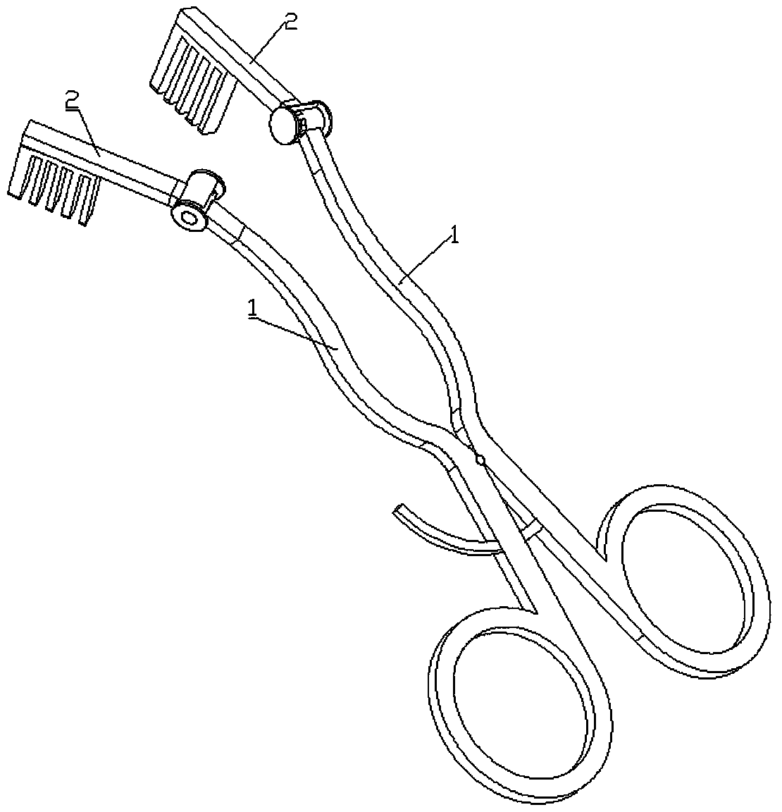
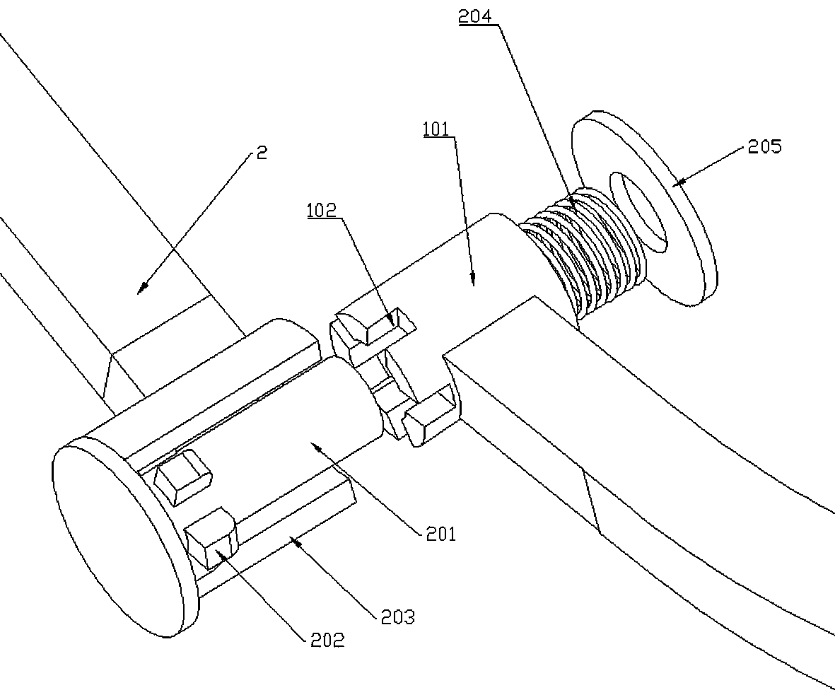
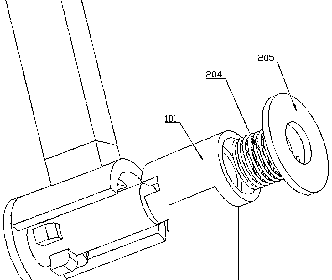
[0021] Embodiment 1: This embodiment discloses a medical retractor, including a handle part 1, two handle parts, the two handle parts are hinged to each other, and the ends of the handle parts are respectively connected with retractor leaves 2, retracting The leaf is used to retract the surgical part to expose the surgical field of view. The connection between the handle and the retracting leaf is a rotating sleeve 101. The rotating sleeve is a hollow structure. The retracting leaf is provided with a rotating core 201 that can go deep into the rotating sleeve 101. The outer wall of the sleeve is provided with a recess 102, and the rotating core is provided with a convex portion 202 that can be snapped into the recess. The rotating core is fixedly connected with a limit head 205. A spring (204) is arranged between the sleeves, and the spring restricts the movement of the rotating core away from the rotating sleeve. The outer layer of the rotating core is provided with a half-rot...

Embodiment 2

[0023] Example 2: A copper-based composite material that can be used to make a retractor. Specifically, 99.99% electrolytic copper is used as a raw material. After vacuum melting, alloy elements are added during the melting process, followed by ingot casting and post-processing molding. The alloy elements include zinc, cobalt, nickel, gallium, silicon, and lanthanum elements, specifically, the weight parts are as follows: 100 parts of copper, 2 parts of zinc, 2 parts of cobalt, 2 parts of nickel, 1 part of gallium, 5 parts of silicon, and 0.1 part of lanthanum , The bending strength of the copper alloy prepared in this way can reach more than 1300Mpa, and the hardness can reach more than 400HV.

Embodiment 3

[0024] Embodiment 3: This embodiment discloses a medical retractor, including a handle part 1, two handle parts, the two handle parts are hinged to each other, and the ends of the handle parts are respectively connected with retractor leaves 2, retracting The leaf is used to retract the surgical part to expose the surgical field of view. The connection between the handle and the retracting leaf is a rotating sleeve 101. The rotating sleeve is a hollow structure. The retracting leaf is provided with a rotating core 201 that can go deep into the rotating sleeve 101. The outer wall of the sleeve is provided with a recess 102, and the rotating core is provided with a convex portion 202 that can be snapped into the recess. The rotating core is fixedly connected with a limit head 205. A spring (204) is arranged between the sleeves, and the spring restricts the movement of the rotating core away from the rotating sleeve. The outer layer of the rotating core is provided with a half-rot...


PUM

PropertyMeasurementUnit
flexural strengthaaaaaaaaaa
hardnessaaaaaaaaaa

Abstract

An embodiment of the invention discloses a medical retractor, and belongs to the field of surgery. The medical retractor comprises two handles. The two handles are hinged to each other, and retractionblades are connected with the ends of the handles and are used for retracting surgical portions and exposing surgical visual fields. The medical retractor is characterized in that rotary sleeves arearranged at joints of the handles and the retraction blades and are of hollow structures, rotary cores capable of deeply extending into the rotary sleeves are arranged on the retraction blades, recesses are formed in the outer walls of the rotary sleeves, protrusions capable of being clamped into the recesses are arranged on the rotary cores, limit heads are fixedly connected with the rotary coresand are not positioned in the directions in which the rotary cores deeply extend into the rotary sleeves, springs are arranged between the limit heads and the rotary sleeves and restrict the rotary cores from moving away from the rotary sleeves, outer layers of the rotary cores are provided with semi-rotary sleeves, partial openings are formed in the semi-rotary sleeves, the rotary cores are fixed to the bottoms of the semi-rotary sleeves, and the semi-rotary sleeves are connected with the retraction blades.

Description

technical field [0001] The invention relates to the field of medical supplies. Background technique [0002] Retractors, also known as retractors, are used to retract tissue to expose the area to be operated for easy exploration and operation. They can be divided into two types: hand-held retractors and automatic retractors. There are various specifications of different shapes and sizes, and the appropriate retractor can be selected according to the operation needs. [0003] Existing retractors usually include two handles and retracting blades, the two handles are hinged to each other to control the blades, and the handle is also provided with a fixing device to fix the position, while the existing blades and the handle are relatively positioned. Fixed, in some cases, it needs to be retracted according to the position of the surgical field of view. If the position is relatively fixed, the operation is more difficult, so a retractor with retractable blades and handles that c...

Claims


Application Information

Patent Timeline
Patent Type & Authority Applications(China)
IPC IPC(8): A61B17/02C22C9/10
CPCA61B17/02A61B2017/00831C22C9/10
Inventor 刘陈邦
Owner 丁汉君
Learn More