Wire feeding type laser material increase manufacturing method

A laser additive and manufacturing method technology, applied in the direction of manufacturing tools, additive processing, laser welding equipment, etc., can solve the problems of low forming efficiency and high reflectivity of laser energy

Active Publication Date: 2018-06-22
BEIJING UNIV OF TECH
View PDF7 Cites 11 Cited by
  • Summary
  • Abstract
  • Description
  • Claims
  • Application Information

AI Technical Summary

Problems solved by technology

[0007] The purpose of the present invention is to provide a method that can improve the forming efficiency of wire-feeding laser add

Method used


Image

  • Wire feeding type laser material increase manufacturing method
  • Wire feeding type laser material increase manufacturing method
  • Wire feeding type laser material increase manufacturing method

Examples


Example Embodiment

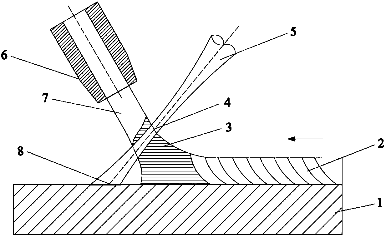
[0043] Embodiment 1: the basic principle of the embodiment of this example sees appendix figure 1, which will not be repeated here. In this example, IPG company YLS-6000 fiber laser is used. The welding wire is made of 316L stainless steel, the diameter of the welding wire is 1.2mm, a 200mm focusing lens is used, and the front wire feeding is adopted. The laser beam and the normal of the workpiece are on the same plane. Adjust the angle between the welding wire and the normal line of the workpiece to be 15°, the angle between the laser beam and the normal line of the workpiece to be 30°, the position of the light spot acting on the welding wire is 2mm away from the surface of the workpiece, the shielding gas is Ar gas, and the gas flow rate is 20L / min. The process parameters are: laser power 3kw, wire feeding speed 3m / min, scanning speed 1.5m / min. Embodiment 1 forming workpiece cross-section OM figure such as attached figure 2 As shown, the forming state of the example of ...

Example Embodiment

[0044] Embodiment 2: the basic principle of the implementation mode of this example sees appendix figure 1 , which will not be repeated here. In this example, IPG company YLS-6000 fiber laser is used. The welding wire is made of 316L stainless steel, the diameter of the welding wire is 1.2mm, a 200mm focusing lens is used, and the front wire feeding is adopted. The laser beam and the normal of the workpiece are on the same plane. Adjust the angle between the welding wire and the normal line of the workpiece to be 30°, the angle between the laser beam and the normal line of the workpiece to be 30°, the position of the light spot acting on the welding wire is 2mm away from the surface of the workpiece, the shielding gas is Ar gas, and the gas flow rate is 20L / min. The process parameters are: laser power 3kw, wire feeding speed 4m / min, scanning speed 1.5m / min. Embodiment 2 forming workpiece cross-section OM figure such as attached image 3 As shown, the forming state of the ex...


PUM


Abstract

The invention provides a wire feeding type laser material increase manufacturing method and a system applying the same, wherein a welding wire and a laser beam are arranged on the two sides of a normal line of a substrate at a certain angle; the laser beam is acted on the welding wire to generate a deep penetration small hole; the welding wire absorbs laser energy in a deep penetration mode to beheated and melted and is transited onto the surface of the substrate to form a cladding layer; and the laser beam, after penetrating through a wire, irradiates the surface of the substrate to preheatthe surface of the substrate in a thermal conductivity mode. According to the wire feeding type laser material increase manufacturing method, the formation efficiency of wire feeding type laser material increase manufacturing can be improved, and the welding wire melting rate is greatly increased by utilizing the deep penetration mode to heat and melt the welding wire; and a workpiece is heated and melted in the thermal conductivity mode, and the defects of small hole type air holes and the like can be effectively avoided from being generated.

Description

technical field [0001] The invention relates to a wire-feeding additive manufacturing method, which belongs to the field of advanced manufacturing technology. Background technique [0002] As an advanced manufacturing technology with low energy consumption, short process, and integration of forming and tissue performance control, laser additive manufacturing has gradually realized laser rapid prototyping and laser direct additive manufacturing since its development in the 1980s. Laser additive manufacturing has changed the forming processing mode of traditional metal parts, especially high-performance parts with complex configurations. Due to its high utilization rate of one-time forming materials, short manufacturing cycle, and excellent performance of formed parts, it is widely used in aerospace, shipbuilding and other fields. [0003] Laser additive manufacturing can be divided into two types according to the different states of metal materials during forming. One is rep...

Claims


Application Information

Patent Timeline
IPC IPC(8): B23K26/342B33Y10/00
CPCB23K26/342B33Y10/00B33Y30/00Y02P10/25
Inventor 肖荣诗肖宁黄婷
Owner BEIJING UNIV OF TECH
Why Eureka
Try Eureka