Environment-friendly sludge conditioning and drying treatment device

A technology for sludge conditioning and drying treatment, which is applied in the direction of temperature control sludge treatment, dehydration/drying/thickened sludge treatment, grain treatment, etc., which can solve the problems that cannot meet the requirements of sludge process

Inactive Publication Date: 2018-06-22
陕西专壹知识产权运营有限公司
6 Cites 5 Cited by

AI-Extracted Technical Summary

Problems solved by technology

[0003] However, with the development of sludge treatment technology, the way of sludge dewatering is also developing. The current technology is more inclined to the deep dehydration of sludge, that is, adding different conditioners (solution state) to sludge before sludge dehydration or solid powder) to condition the sludge to improve the dewatering perform...

Abstract

The invention discloses an environment-friendly sludge conditioning and drying treatment device and belongs to the technical field of sludge treatment equipment. The environment-friendly sludge conditioning and drying treatment device comprise a chemical preparation device, a conditioning device, a dehydration drying device and a control device. The amount of sludge entering a drying drum can be metered precisely, and overload of the dehydration drying device is avoided; meanwhile, drying is performed by means of hot flue gas, and energy is used reasonably; the sludge is smashed uniformly by astirring push rod in a drying process and is pushed to advance, the drying process is uniform, the hot flue gas makes full contact with the sludge, the drying effect is good, the drying process is continuous and efficient, a secondary drying device is arranged, heat of wet flue gas is fully used, the energy use rate is high, and the drying effect is obvious.

Application Domain

Sludge treatment by de-watering/drying/thickeningSludge treatment by thermal conditioning +1

Technology Topic

Flue gasChemical preparation +4

Image

  • Environment-friendly sludge conditioning and drying treatment device
  • Environment-friendly sludge conditioning and drying treatment device
  • Environment-friendly sludge conditioning and drying treatment device

Examples

  • Experimental program(1)

Example Embodiment

[0020] The present invention is achieved through the following technical solutions:
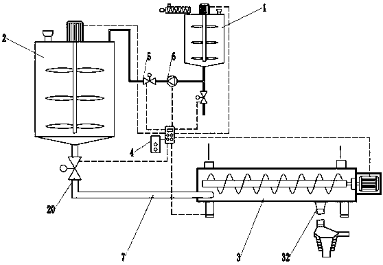
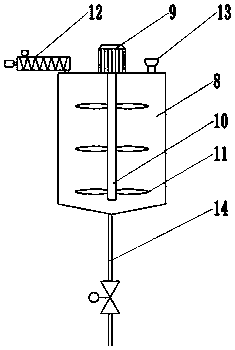
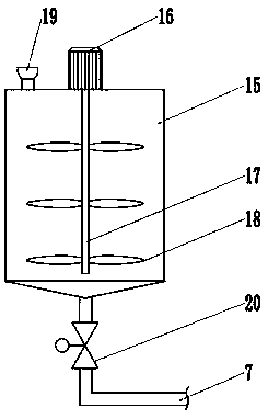
[0021] See Figure 1-7 , An environmentally friendly sludge conditioning and drying treatment device, comprising a medicament dispensing device 1, a conditioning device 2, a dehydration drying device 3, and a control device 4. The outlet end of the medicament dispensing device 1 is connected to the conditioning device 2, so At least one outlet valve 5 and an electromagnetic pump 6 are connected between the medicament dispensing device 1 and the conditioning device 2. The conditioning device 2 and the dehydration drying device 3 are connected by a mud outlet pipe 7; the medicament dispensing device 1 includes a dispensing tank 8, a first motor 9, a first stirring shaft 10, a first stirring blade 11, a solid medicine feeder 12, a liquid medicine inlet 13 and a liquid discharge port 14. The first motor 9 is fixed at Above the dispensing tank 8, the first stirring shaft 10 is fixed to the output end of the first motor 9 and extends into the dispensing tank 8, the first stirring blade 11 is fixed on the first stirring shaft 10, and the solid medicine The medicine feeder 12 and the liquid medicine inlet 13 are respectively installed at the top of the dispensing tank 8, and the liquid discharge port 14 is fixed at the bottom of the dispensing tank 8. The conditioning device 2 includes a conditioning tank 15, a second motor 16, and a second motor. The second mixing shaft 17, the second mixing blade 18 and the mud inlet 19, the second motor 16 is fixed above the conditioning tank 15, and the second mixing shaft 17 is fixed to the output end of the second motor 16 and extends into the conditioning tank. Inside the tank 15, the second mixing blade 18 is fixed on the second mixing shaft 17, the mud inlet 19 is installed at the top of the conditioning tank 15, and the bottom of the conditioning tank 15 is connected to the mud outlet pipe 7; The output ends of a motor 9, the second motor 16, the outlet valve 5, and the electromagnetic pump 6 are electrically connected to the input ends of the control device 4, respectively.
[0022] A mud outlet valve 20 is installed on the mud outlet pipe 7, and the input end of the mud outlet valve 20 is electrically connected to the output end of the control device 4.
[0023] The dehydration and drying device 3 includes a drying drum 21, a third motor 22, a third stirring shaft 23, a spiral pushing blade 24, an air inlet 25 and an air outlet 26. The drying drum 21 is placed horizontally, and the first Three motors 22 fix one side of the drying drum 21, the third stirring shaft 23 is installed at the power output end of the third motor 22 and extends into the drying drum 21, and the screw pushing blade 24 is fixed on the third stirring shaft. On the shaft 23, the air inlet 25 and the air outlet 26 are respectively fixed on the drying cylinder 21 for hot air flow in and wet air flow out.
[0024] A frame 27 is fixed at the bottom of the drying drum 21, a support frame 28 is installed under the frame 27, and a pressure sensor 29 is installed between the frame and the support frame 28.
[0025] The control device 4 includes a single chip microcomputer 30 and a display 31. The output terminal of the single chip microcomputer 30 is electrically connected to the input terminal of the display 31, and the input terminal of the single chip computer 30 is electrically connected to the output terminal of the pressure sensor 29.
[0026] A sludge discharge port 32 is installed at the bottom of the drying cylinder 21, a sludge discharge wheel 33 is installed above the sludge discharge port 32, and a drying separation cylinder 34 is installed at the bottom of the sludge discharge port 32. The outside of the drying separation cylinder 34 is a coiled heating tube 35, and the upper and bottom of the drying separation cylinder 34 are fixed with a moisture discharge port 36 and a discharge port 37.
[0027] Working principle: Firstly, the sludge is driven into the conditioning tank 15, the conditioning device 2 is turned on through the control device 4, so that the sludge is stirred uniformly; the conditioning agent is added to the dispensing tank 8, and the mixing of the medicine dispensing device 1 is set by the control device 4 Speed ​​and stirring time, after the conditioning agent is uniformly configured, the control device 4 opens the liquid outlet valve 5, adds the conditioning agent to the conditioning tank 8, and controls the dosage of the conditioning agent through the electromagnetic pump 6; then the control device 4 turns on the solid agent delivery The medicine device 12 adds the solid conditioning agent to the conditioning tank 8 through the solid medicine feeder 12, and obtains the dosed conditioning dose through the display of the solid medicine feeder 12; after the conditioning agent is added, it is set by the control device 4 The mixing speed and mixing time of the conditioning device 2 are used for sludge conditioning; after the sludge conditioning is completed, the sludge outlet valve 20 of the sludge outlet pipe at the bottom of the conditioning tank 8 is opened, and the conditioned sludge is sent to the sludge outlet pipe 7 for dehydration and drying Device 3, for deep dehydration; the dry hot air enters from the air inlet, and the sludge containing a large amount of water enters from the sludge inlet 19, and is initially crushed under the action of the screw propeller blade 24, and then gradually advances. During this process, the dry hot air flow enters the drying cylinder 21 from the air inlet 25 to contact the sludge, heat the sludge at high temperature, and the water in the sludge evaporates and mixes into the hot air flow to form a humid air flow, and finally reach the air outlet 26. The sludge advances and reaches the sludge discharge port 32, then discharges downwards, and enters the drying separation drum 34. In the drying separation drum 34, the sludge is reheated and evaporated to dryness through the wall of the drying separation drum 34. The water in the sludge in the chemical separation drum 34 evaporates, and the water vapor is discharged through the moisture discharge port 36; after the sludge is dried for the second time, it falls through the discharge port 37 to complete the drying.

PUM

no PUM

Description & Claims & Application Information

We can also present the details of the Description, Claims and Application information to help users get a comprehensive understanding of the technical details of the patent, such as background art, summary of invention, brief description of drawings, description of embodiments, and other original content. On the other hand, users can also determine the specific scope of protection of the technology through the list of claims; as well as understand the changes in the life cycle of the technology with the presentation of the patent timeline. Login to view more.
Why Eureka
Try Eureka