After-treatment intake mixing device

A mixing device and air intake technology, which is applied in the direction of exhaust device, exhaust treatment, noise reduction device, etc., can solve the problem of unfavorable mixing of urea droplets, dead air flow, and short mixing path of exhaust gas and urea droplets in the single-layer intake pipe And other issues

Inactive Publication Date: 2018-06-22
WEICHAI POWER CO LTD +1
View PDF7 Cites 11 Cited by
  • Summary
  • Abstract
  • Description
  • Claims
  • Application Information

AI Technical Summary

Problems solved by technology

[0005] (1) The intake mixing tube itself is a single-layer tube with a single opening form, which is not conducive to the generation of turbulent flow and the mixing between exhaust gas and urea droplets. The conversion efficiency of urea into NH3 is not high, and the undecomposed urea droplets prone to crystallization
[0006] (2) The mixing path of exhaust gas and urea droplets in the intake single-layer pipe is short, and the urea droplets that cannot be fully broken are easy to form urea crystals in the intake mixing chamber
[0007] (3) The airflow dead zone is easy to form at the end connection of the single-layer intake pipe, and the risk of crystallization is high
[0008] (4) Poor thermal insulation effect and low heat utilization rate

Method used


Image

  • After-treatment intake mixing device
  • After-treatment intake mixing device
  • After-treatment intake mixing device

Examples


Embodiment Construction

[0034] In order to make the purpose, technical solutions and advantages of the embodiments of the present invention clearer, the technical solutions in the embodiments of the present invention will be clearly and completely described below in conjunction with the drawings in the embodiments of the present invention. Obviously, the described embodiments It is a part of embodiments of the present invention, but not all embodiments. Based on the embodiments of the present invention, all other embodiments obtained by persons of ordinary skill in the art without making creative efforts belong to the protection scope of the present invention.

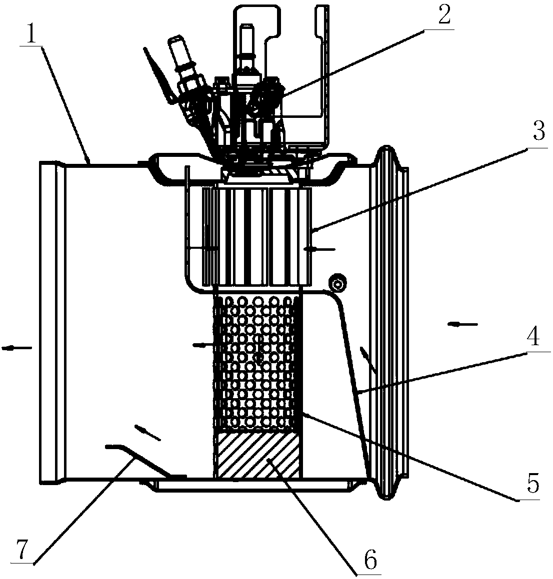
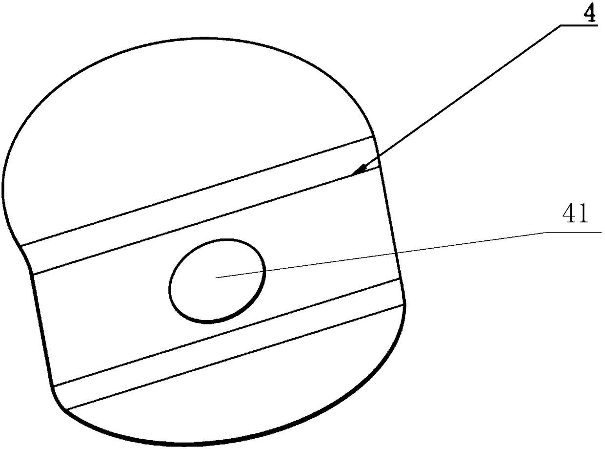
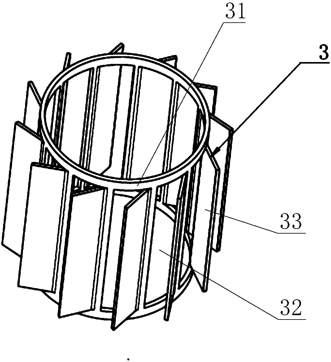
[0035] Please refer to Figure 1-Figure 5 , figure 1 Schematic diagram of the structure of the post-treatment intake air mixing device provided by the embodiment of the present invention; figure 2 Schematic diagram of the structure of the air intake deflector provided by the embodiment of the present invention; image 3 Schematic diagram ...


PUM


Abstract

The invention discloses an after-treatment intake mixing device. The after-treatment intake mixing device comprises a bucket body, a urea injection device, an intake swirl sheet and an intake mixing pipe, wherein the intake sheet blade comprises a barrel body; a first through hole is formed in the barrel wall of the barrel body; an inclined sheet is arranged on the first through hole; a urea nozzle of the urea injection device is aligned with the inner ring of the intake swirl sheet; the intake swirl sheet is butted with the intake mixing pipe; and a plurality of second through holes are formed in the intake mixing pipe. Tail gas enters from an intake port of the bucket body, and swirl mixing is carried out on the tail gas and an aqueous urea solution injected through the urea nozzle in the intake swirl sheet; the swirl sheet is beneficial to adequate mixing for the tail gas and mist urea liquid drops; and the mixed gas flow enters the intake mixing pipe, directly flows out through thesecond through holes in the intake mixing pipe, and contacts with a carrier with an SCR catalyst to carry out a catalytic reduction reaction. The intake swirl sheet enables the gas flow to form effective vortex, so that the collision probability of the tail gas and the aqueous urea solution is increased, and then the conversion efficiency of nitrogen oxides is increased.

Description

technical field [0001] The invention relates to the technical field of engine exhaust gas treatment, in particular to an aftertreatment intake air mixing device. Background technique [0002] The SCR catalytic reduction technology used in engine exhaust treatment in the prior art is an important technical route to reduce nitrogen oxide emissions from diesel engines and meet the national IV and above emission regulations. The currently applied design scheme often has phenomena such as emission failure and urea crystallization, which lead to an increase in the failure rate of the engine, a decline in customer satisfaction, and even fail to meet the requirements of national emission regulations. [0003] The method adopted in the prior art for engine exhaust gas treatment is that the exhaust gas flow directly enters the intake mixing pipe, and is mixed with the urea aqueous solution sprayed by the urea nozzle of the urea injection device in the intake mixing pipe, and the mixed...

Claims


Application Information

Patent Timeline
Patent Type & Authority Applications(China)
IPC IPC(8): F01N3/28F01N3/20
CPCF01N3/208F01N3/28F01N3/2892F01N2610/02F01N2610/1453Y02T10/12
Inventor 李昭阳卞增涛王奉双李俊普
Owner WEICHAI POWER CO LTD
Why Eureka
Try Eureka