Balloon catheter
A balloon catheter and balloon technology, which can be applied to balloon catheters, catheters, pretreated surfaces, etc., can solve problems such as poor performance of crossing lesions and easy damage to blood vessels, and achieve improved surface smoothness, reduced friction, and reduced The effect of decompression time
- Summary
- Abstract
- Description
- Claims
- Application Information
AI Technical Summary
Problems solved by technology
Method used
Image
Examples
Embodiment 1
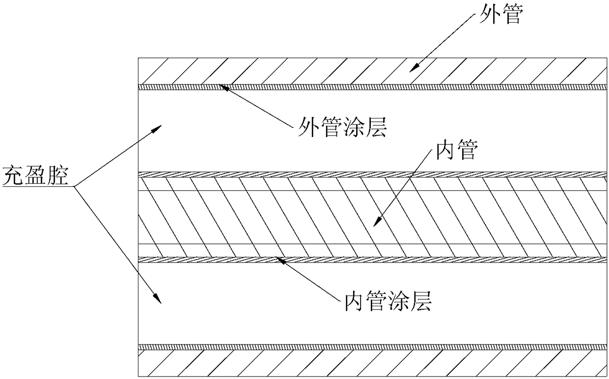
[0034] See figure 1 , a balloon catheter (specification 7.0×120), comprising an inner tube 4, a balloon 1, a developing ring 2, an outer tube 3 and a catheter seat 5, the developing ring 2 is crimped and embedded in the inner tube 4, and the distal end of the inner tube 4 The distal end of the outer tube 3 is fixed in the distal end of the balloon 1 , the distal end of the outer tube 3 is fixed in the proximal end of the balloon 1 , and the proximal end of the outer tube 3 is fixed in the catheter adapter 5 .
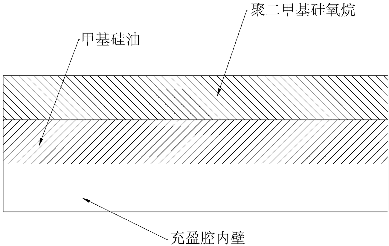
[0035] Please refer to figure 2 and image 3 , the inner wall of the outer tube 3 and the outer wall of the inner tube 4 are coated with a coating, the coating includes a methyl silicone oil layer and a polydimethylsiloxane layer, and the methyl silicone oil layer is arranged on the inner wall / inside of the outer tube 3 Between the outer wall of the tube 4 and the layer of polydimethylsiloxane.
[0036] The methyl silicone oil layer of the inner tube 4 is obtained b...
Embodiment 2
[0043] The balloon catheter of this embodiment has a similar structure to the balloon catheter of Embodiment 1, the difference is that:
[0044] The methyl silicone oil layer of the inner tube is obtained by the following coating method: the inner tube is soaked in methyl silicone oil (viscosity 5) containing UV curing agent 3091 for 15 seconds and then subjected to ultraviolet light (ultraviolet light intensity is 30mw / cm 2 ) was cured for 30s to obtain a methyl silicone oil layer; the quality of the UV curing agent 3091 was 0.4% of the quality of the methyl silicone oil.
[0045] The methyl silicone oil layer of the outer tube is obtained by the following coating method: Inject (injection speed: 30mm / s) methyl silicone oil (viscosity: 5) containing UV curing agent 3091 into the inner cavity of the outer tube for 15s and then perform ultraviolet light (ultraviolet light Strength is 30mw / cm 2 ) was cured for 30s to obtain a methyl silicone oil layer; the quality of the UV cur...
Embodiment 3
[0050] The balloon catheter of this embodiment has a similar structure to the balloon catheter of Embodiment 1, the difference is:
[0051] The methyl silicone oil layer of the inner tube is obtained by the following coating method: the inner tube is immersed in methyl silicone oil (viscosity 5) containing UV curing agent 3091 for 22 seconds and then subjected to ultraviolet light (ultraviolet light intensity is 35mw / cm 2 ) was cured for 32s to obtain a methyl silicone oil layer; the mass of the UV curing agent 3091 was 0.4% of the mass of the methyl silicone oil.
[0052] The methyl silicone oil layer of the outer tube is obtained by the following coating method: Inject (injection speed 35mm / s) methyl silicone oil (viscosity 5) containing UV curing agent 3091 into the inner cavity of the outer tube for 22s and then perform ultraviolet light (ultraviolet light Strength is 35mw / cm 2 ) was cured for 32s to obtain a methyl silicone oil layer; the mass of the UV curing agent 3091...
PUM
 Abstract
Description
Claims
Application Information
 - R&D
- Intellectual Property
- Life Sciences
- Materials
- Tech Scout
- Unparalleled Data Quality
- Higher Quality Content
- 60% Fewer Hallucinations
Browse by: Latest US Patents, China's latest patents, Technical Efficacy Thesaurus, Application Domain, Technology Topic, Popular Technical Reports.
© 2025 PatSnap. All rights reserved.Legal|Privacy policy|Modern Slavery Act Transparency Statement|Sitemap|About US| Contact US: help@patsnap.com


