Screw rod adjusting type automatic oiling device for rotating shafts of direct-current coil motor

A technology of a motor shaft and an oiling device, which is applied to devices and coatings that apply liquid to the surface, can solve the problems of difficulty in oiling the shaft, cannot be reused, waste resources, etc., so as to avoid insufficient oiling, The effect of improving utilization and improving efficiency

Inactive Publication Date: 2018-06-29
台州来智科技有限公司
View PDF4 Cites 4 Cited by
  • Summary
  • Abstract
  • Description
  • Claims
  • Application Information

AI Technical Summary

Problems solved by technology

The difference between brushless DC fan coils and traditional fan coils is that brushless DC fan coils have the advantages of energy saving, stepless speed regulation, quietness, and long life, so they are widely used in many new construction projects, and are also It is more and more recognized and favored by the market, and the motor used in the DC coil motor is generally a double-shaft motor. Due to the long length of the shaft of the double-shaft motor, it is difficult to apply oil to the shaft, and the effect of manual coating is not good. Good, the phenomenon of missing coating often occurs, because the shafts of the air duct machine are not the same, so a shaft that can meet the requirements of different lengths is needed for oiling, and at the same time, it can also carry out multi-station oiling, so as to improve the efficiency of oiling. Moreover, in the existing oiling device, after oiling, the excess liquid antirust oil is collected and processed, which cannot be reused and wastes resources.

Method used


Image

  • Screw rod adjusting type automatic oiling device for rotating shafts of direct-current coil motor
  • Screw rod adjusting type automatic oiling device for rotating shafts of direct-current coil motor
  • Screw rod adjusting type automatic oiling device for rotating shafts of direct-current coil motor

Examples


Embodiment Construction

[0020] The technical solution of this patent will be further described in detail below in conjunction with specific embodiments.

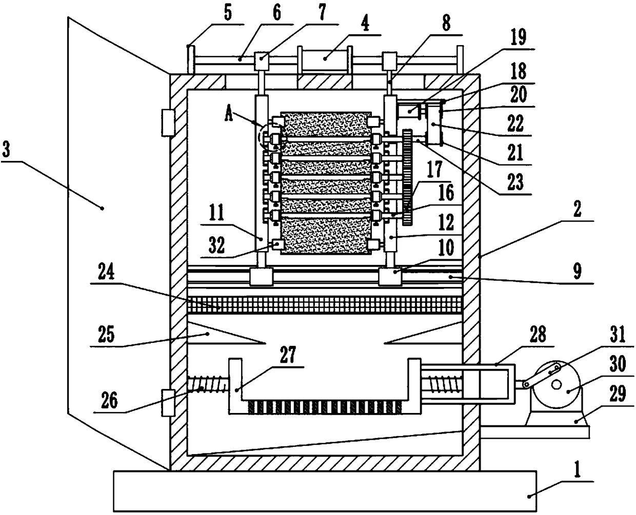
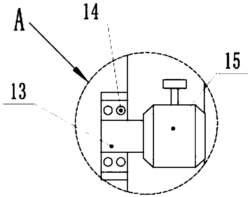
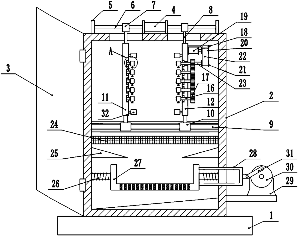
[0021] see Figure 1-3 , a screw-screw adjustable DC coil motor shaft automatic oiling device, comprising a base 1, a first drive motor 4, a first vertical plate 11, a second vertical plate 12, a coupling 15, a second drive motor 19 and Filter tank 27, the upper surface of the base 1 is fixedly equipped with a device box 2, which is fixedly connected by screws between the device box 2 and the base 1, and the left side of the device box 2 is hingedly equipped with a box door 3, and the upper surface of the device box 2 The first drive motor 4 is fixedly installed at the side center position, and the first drive motor 4 is a biaxial motor, and the output shafts at both ends of the first drive motor 4 are fixedly connected with a screw rod 6 through a coupling, and the device box 2 The left and right parts of the upper side are symmetrically provided...


PUM


Abstract

The invention discloses a screw rod adjusting type automatic oiling device for rotating shafts of a direct-current coil motor. The screw rod adjusting type automatic oiling device comprises a base, afirst driving motor, a first vertical plate, a second vertical plate, couplings, a second driving motor and a filtering tank. A transverse rod is horizontally arranged in a device box. The filtering tank is slidably mounted on the transverse rod. A pull rod is welded on the right side of the filtering tank. A third driving motor is fixedly mounted on the right side of the device box through a support. An output shaft of the third driving motor is faced forward, and a rotating wheel is mounted on the output shaft of the third driving motor in an interference fit manner. A second connecting rodis rotationally and eccentrically mounted on the front surface of the rotating wheel. The other end of the second connecting rod is hinged to the pull rod. By the adoption of the rotating shaft oilingdevice, excess anti-rust oil can be collected into the filtering tank, and then by indirectly driving the filtering tank to move left and right, the filtering speed of the anti-rust oil is increasedgreatly; meanwhile, the filtered anti-rust oil can be reused, the utilization rate of the anti-rust oil is increased greatly, and the cost is saved.

Description

technical field [0001] The invention relates to the field of electric motors, in particular to an automatic oiling device for a rotating shaft of a screw adjustable DC coil motor. Background technique [0002] The DC brushless fan coil unit is a fan coil unit that uses a DC brushless motor and a large-screen LCD temperature controller. The difference between brushless DC fan coils and traditional fan coils is that brushless DC fan coils have the advantages of energy saving, stepless speed regulation, quietness, and long life, so they are widely used in many new construction projects, and are also It is more and more recognized and favored by the market, and the motor used in the DC coil motor is generally a double-shaft motor. Due to the long length of the shaft of the double-shaft motor, it is difficult to apply oil to the shaft, and the effect of manual coating is not good. Good, the phenomenon of missing coating often occurs, because the shafts of the air duct machine ar...

Claims


Application Information

Patent Timeline
Patent Type & Authority Applications(China)
IPC IPC(8): B05C1/02B05C11/10B05C13/02
CPCB05C1/02B05C11/1039B05C13/025
Inventor 郑贝贝
Owner 台州来智科技有限公司
Why Eureka
Try Eureka