Punching method of low-plasticity high-silicon aluminum alloy strip

A high-silicon aluminum alloy and low plasticity technology, which is applied in the field of mechanical processing, can solve the problems of reducing the service life of punching dies, wearing the edge of punching dies, increasing punching costs, etc., to reduce strength, strengthen hydrostatic pressure, prevent The effect of cross-sectional cracks

Inactive Publication Date: 2018-06-29
有研科技集团有限公司
4 Cites 1 Cited by

AI-Extracted Technical Summary

Problems solved by technology

Before the high-silicon aluminum alloy strip is applied to a key part of the car, it needs to be punched to facilitate assembly on the car; due to the high strength and low plasticity of the high-silicon aluminum alloy, the existing co...

Abstract

The invention belongs to the technical field of machining, and particularly relates to a punching method of a low-plasticity high-silicon aluminum alloy strip. The punching method includes the steps:heating the high-silicon aluminum alloy strip to reach the temperature of 200-350 DEG C, and punching the heated high-silicon aluminum alloy strip; designing the depth of a punching die guide groove to account for 30%-70% of the thickness t of the high-silicon aluminum alloy strip, designing the gap between a punched female die and a punched male die to be 12-15% t, and designing the bottom of a punched die cutting edge into a round angle with the radius r of 0.2-0.5mm. By the punching method, punching effect with high-accuracy cross section quality can be acquired, punching efficiency is improved, the service life of a punching die is prolonged, and production cost is reduced.

Application Domain

Technology Topic

Image

  • Punching method of low-plasticity high-silicon aluminum alloy strip
  • Punching method of low-plasticity high-silicon aluminum alloy strip
  • Punching method of low-plasticity high-silicon aluminum alloy strip

Examples

  • Experimental program(4)

Example Embodiment

[0024] Example 1
[0025] Punching the high-silicon aluminum alloy strip with chemical composition Si 19wt%, Cu 4wt%, Fe 5.5wt%, Mg 1.5wt%, and the balance being Al, the specific process includes the following steps:
[0026] (1) Take a high-silicon aluminum alloy strip with a thickness t of 4.2mm and heat it to 320°C;
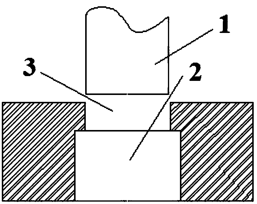
[0027] (2) Put the heated high-silicon aluminum alloy strip in the guide groove 3 of the punching die, guide and position the strip, and fix it with a pressing head, start the press, and set the punching die 2 and punch 1 Under the action of the cutting edge, the high silicon aluminum alloy strip is punched and blanked; the depth of the punching die guide groove 3 is 3.8mm, the gap between the die 2 and the punch 1 is 0.05mm, and the punching die blade The bottom of the mouth has small rounded corners, and the rounded corner radius r is 0.2mm;
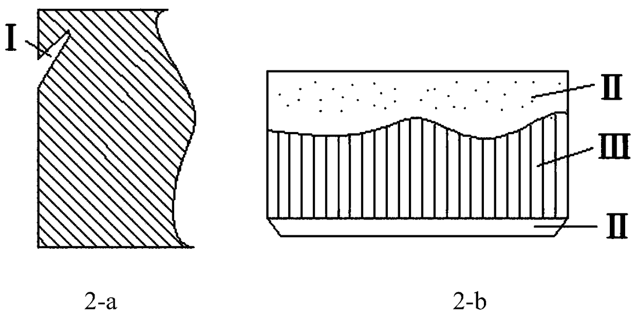
[0028] The cross-sectional effect diagram of the high silicon aluminum alloy strip obtained by the above punching method is as follows image 3 As shown on the right in -a, the cross-sectional effect diagram obtained by directly punching the strip without heating the strip is as follows image 3 -a shown on the left; from image 3 -a It can be seen that the fracture zone on the left section has a larger area and has obvious tear cracks. In contrast, the quality of the section obtained in Example 1 is good, and no obvious tear appears.

Example Embodiment

[0029] Example 2
[0030] Punching the high silicon aluminum alloy strip with chemical composition Si 16.8wt%, Cu 4.3wt%, Fe 5wt%, Mg 1.4wt%, and the balance being Al, the specific process includes the following steps:
[0031] (1) Take a high-silicon aluminum alloy strip with a thickness t of 5.5mm and heat it to 330°C;
[0032] (2) Put the heated high-silicon aluminum alloy strip in the guide groove of the punching die, guide and position the strip, and fix it with a pressing head, start the press, and set the punching die 2 and punch 1 Under the action of the cutting edge, the high silicon aluminum alloy strip is punched and blanked; the depth of the guiding groove 3 of the punching die is 5.3mm, the gap between the die 2 and the punch 1 is 0.07mm, and the cutting edge of the die The bottom is small rounded corners, and the rounded corner radius r is 0.5mm;
[0033] The cross-sectional effect diagram of the high silicon aluminum alloy strip obtained by the above punching method is as follows image 3 As shown on the right in -b, the cross-sectional effect diagram obtained by directly punching the strip without heating the strip is as follows image 3 -b shown on the left; from image 3 -b It can be seen that the smoothness of the left section is low, and the fracture zone at the edge position occupies a large area. In contrast, the section obtained in Example 2 has no burrs and the fracture zone occupies a small area.

Example Embodiment

[0034] Example 3
[0035] Punching a high-silicon aluminum alloy strip with chemical composition Si 18wt%, Cu 3.5wt%, Fe 5wt%, Mg 1wt%, and the balance being Al, the specific process includes the following steps:
[0036] (1) Take a high-silicon aluminum alloy strip with a thickness t of 5mm and heat it to 300°C;
[0037] (2) Put the heated high-silicon aluminum alloy strip in the guide groove 3 of the punching die, guide and position the strip, and fix it with a pressing head, start the press, and set the punching die 2 and punch 1 Under the action of the cutting edge, the high-silicon aluminum alloy strip is punched and blanked; the depth of the punching die guide groove 3 is 4.4mm, the gap between the die 2 and the punch 1 is 0.06mm, and the punching die blade The bottom of the mouth is a small rounded corner, and the rounded corner radius r is 0.3mm;
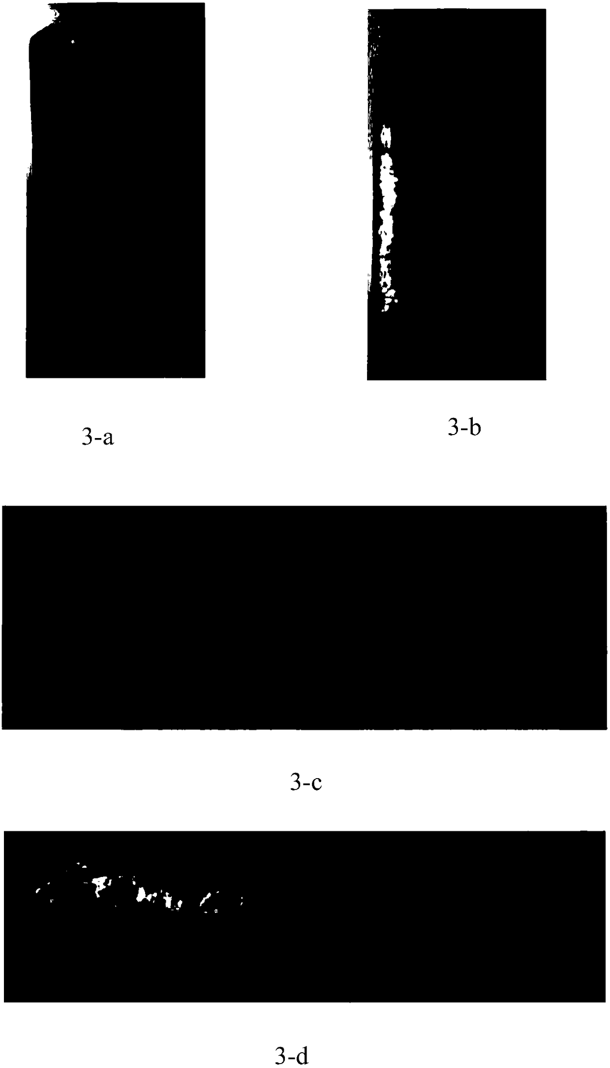
[0038] The cross-sectional effect diagram of the high silicon aluminum alloy strip obtained by the above punching method is as follows image 3 As shown on the right in -c, the cross-sectional effect diagram obtained by directly punching the strip without heating the strip is as follows image 3 -c shown on the left; from image 3 -c It can be seen that the burr is obvious on the left section, the area of ​​the fracture zone at the vertical plane is larger, and the tear cracks are very obvious. In contrast, the section obtained in Example 3 has good quality, no burrs, and a small area of ​​the fracture zone.

PUM

PropertyMeasurementUnit
Thickness3.0 ~ 5.5mm
Corner radius0.2 ~ 0.5mm
tensileMPa
Particle sizePa
strength10

Description & Claims & Application Information

We can also present the details of the Description, Claims and Application information to help users get a comprehensive understanding of the technical details of the patent, such as background art, summary of invention, brief description of drawings, description of embodiments, and other original content. On the other hand, users can also determine the specific scope of protection of the technology through the list of claims; as well as understand the changes in the life cycle of the technology with the presentation of the patent timeline. Login to view more.

Similar technology patents

Classification and recommendation of technical efficacy words

Why Eureka
Try Eureka