
Punching die for automobile covering parts

A technology for automobile cover parts and punching, which is applied in the direction of perforating tools, cleaning methods and tools, manufacturing tools, etc., which can solve the problems of high processing difficulty, lack of power for lateral movement, difficult processing, etc., and it is difficult to control the precision and precise control , Processing precise effect

Inactive Publication Date: 2018-06-29
CHONGQING YINSHENG MOLD
View PDF0 Cites 6 Cited by
  • Summary
  • Abstract
  • Description
  • Claims
  • Application Information

AI Technical Summary

Problems solved by technology

However, this device has the following problems: due to the irregularity of the car cover, the central axis of the required hole is inclined, not perpendicular to the plane where the drill bit is located, and it is not easy to process
[0004] In order to solve the above problems, there is a drilling device with the drill bit tilted, but the cylinder that drives the drill bit can only give the drill bit the power to move downward. The resistance in both longitudinal directions, while the drill bit is only powered by longitudinal movement, without the power of lateral movement, the transverse resistance on the drill bit can easily break the drill bit
Even if the cylinder is tilted, it is difficult to precisely control the tilt angle, it is difficult to ensure the correct position of the hole and the accuracy requirements, and the processing is very difficult

Method used


Image

  • Punching die for automobile covering parts
  • Punching die for automobile covering parts

Examples


Embodiment Construction

[0023] The following is further described in detail through specific implementation methods:

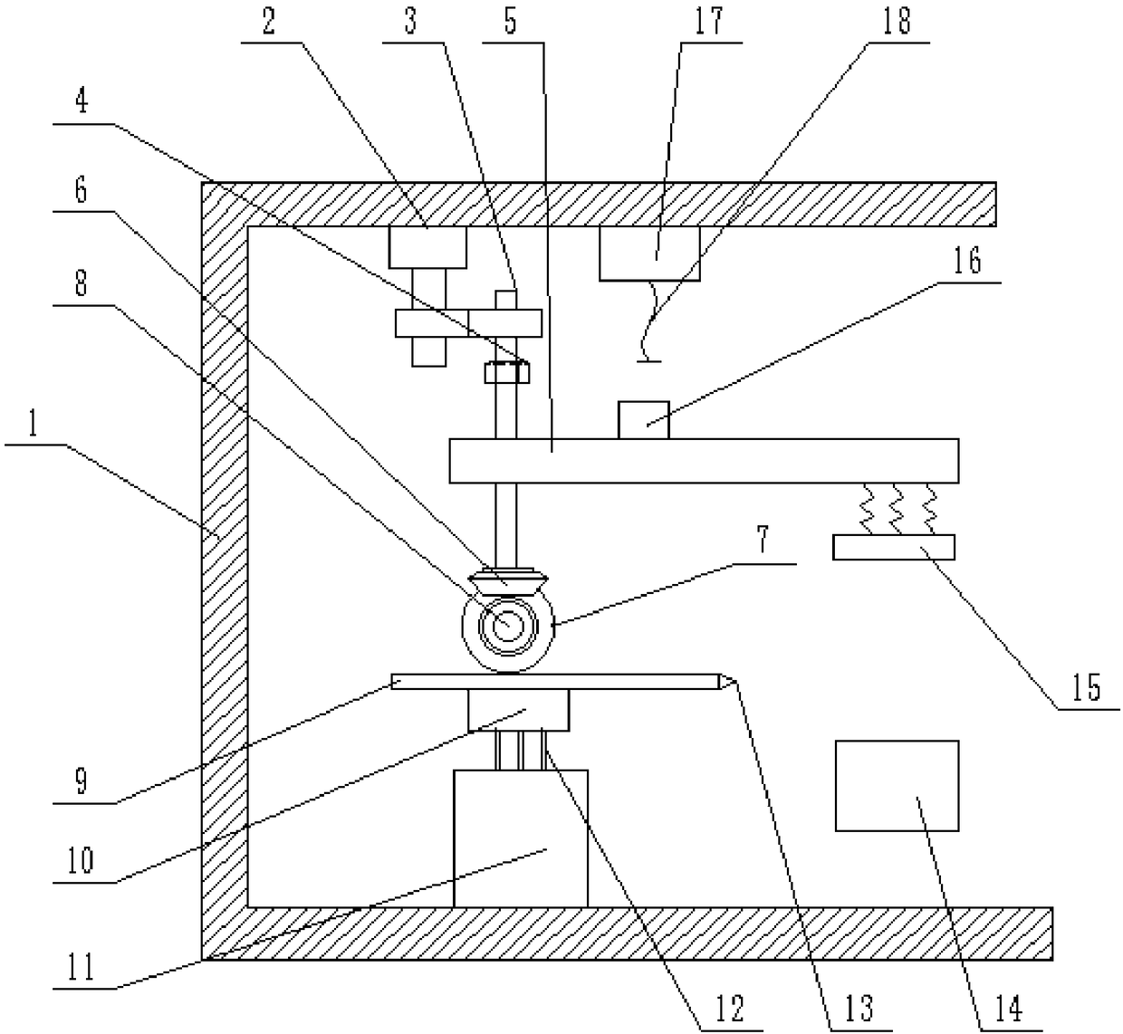
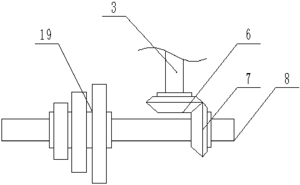
[0024] The reference signs in the drawings of the description include: frame 1, rotating motor 2, first rotating shaft 3, nut 4, upper mold base 5, first bevel gear 6, second bevel gear 7, second rotating shaft 8, rack 9. Fixed seat 10, piston barrel 11, piston rod 12, drill bit 13, lower mold base 14, pressing plate 15, electromagnet 16, power supply 17, wire 18, triple gear 19.

[0025] Such as figure 1 As shown, the mold for punching an automobile cover part includes a frame 1, and the frame 1 is provided with a first rotating shaft 3 and a rotating motor 2, and the first rotating shaft 3 includes a spline section, a thread section and In the clamping section, a spline sleeve is connected outside the spline section, and a driven gear is connected outside the spline sleeve. The output shaft of the rotary motor 2 is provided with a driving gear meshing with the driven gear. A nut ...


PUM


Abstract

The invention belongs to the field of dies for automobile part processing and particularly discloses a punching die for automobile covering parts. The punching die comprises a frame, an upper die baseand a lower die base are arranged on the frame, a power source is arranged at the top of the frame and connected with a wire, a first electrode plate is connected to the lower end of the wire, the upper die base is provided with an electromagnet below the wire, and a second electrode plate is arranged on the electromagnet. A first rotating shaft comprises a spline section, a threaded section anda clamping section sequentially from top to bottom, the spline section is externally connected with a spline sleeve, a first bevel gear is arranged at the bottom of the first rotating shaft, a secondbevel gear meshed with the first bevel gear is arranged on the second rotating shaft which is further provided with a multiplex gear. A rack meshed with the multiplex gear is in slide connection withthe top end of a fixing seat, the fixing seat is provided with magnets on two sides of the rack, and a drill bit is connected to one end, close to the lower die base, of the rack. By adoption of the scheme, the inclined hole processing requirement of the drill bit is met.

Description

technical field [0001] The invention belongs to the field of molds for processing automobile parts, and specifically discloses a mold for punching automobile cover parts. Background technique [0002] Automobile panels refer to the surface or internal parts of the space shape made of metal sheets covering the engine, chassis, cab, and body. Automobile panels are mostly two-dimensional curved surfaces with large sizes and complex shapes. It not only requires high appearance quality , and in order to ensure the quality of welding and assembly, the requirements for matching accuracy, consistency of shape and size, and interchangeability are very high. Therefore, the stamping equipment, molds and raw materials used in the production of automotive panels are different from those of general stamping parts production. [0003] Among them, the basic processes of stamping and forming of automotive panels include: blanking, pre-bending, drawing, trimming, punching, flanging, shaping,...

Claims


Application Information

Patent Timeline
IPC IPC(8): B21D28/26B21D43/00B21D28/34B08B15/04B03C1/02
CPCB21D28/26B03C1/02B08B15/04B21D28/34B21D43/003
Inventor 邱建华
Owner CHONGQING YINSHENG MOLD
Learn More