Shuttle air draft guide rail of shuttle loom

A technology for air-floating guide rails and shuttle looms, applied in looms, textiles, textiles and papermaking, etc., can solve the problems of unstable power consumption, affecting work progress, waste of resources, etc., so as to improve the textile effect and reduce the waste of resources. , Improve the effect of work progress

Pending Publication Date: 2018-06-29
王广和 +1
View PDF4 Cites 0 Cited by
  • Summary
  • Abstract
  • Description
  • Claims
  • Application Information

AI Technical Summary

Problems solved by technology

[0003] The existing magnetic levitation shuttle machine is expensive, unstable in power consumption, and wastes resources due to high energy consumption, which fails to meet the requirements of the national energy conservation; because the heavier the shuttle, the better the textile effect within a certain range, and the existing magnetic levitation The shuttle in the middle reaches 5 catties, and it cannot continue to increase; and the magnetic levitation uses multiple or single electromagnets to provide force, and the magnetic force is uneven, which may easily cause the weaving thread to be cut off during weaving, causing the machine to suspend work, thereby affecting the work progress.

Method used


Image

  • Shuttle air draft guide rail of shuttle loom
  • Shuttle air draft guide rail of shuttle loom
  • Shuttle air draft guide rail of shuttle loom

Examples


Embodiment 1

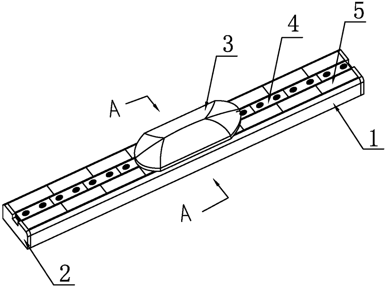
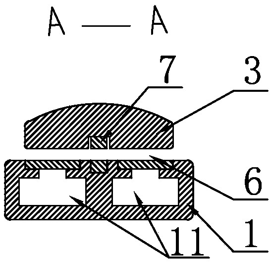
[0029] For the shuttle air-floating guide rail of a shuttle loom provided in Embodiment 1 of the present invention, please refer to figure 1 As shown, it includes an air-floating guide rail 1 and a shuttle 3 suspended above the air-floating guide rail 1. The top extension direction of the air-floating guide rail 1 is provided with a number of first permanent magnets 4 and is arranged on the first permanent magnet. Some porous ceramics 5 on both sides of the magnet 4, and some of the porous ceramics 5 on both sides are symmetrical to each other with the first permanent magnet 4 as the axis of symmetry; please refer to figure 2 As shown, there are two compressed air flow grooves 11 inside the air flotation guide rail 1, and the two compressed air flow grooves 11 communicate with the plurality of porous ceramics 5 on both sides respectively; the compressed air flow grooves 11 are externally connected to Air compressor; the two ends of the air-floating guide rail 1 are respective...

Embodiment 2

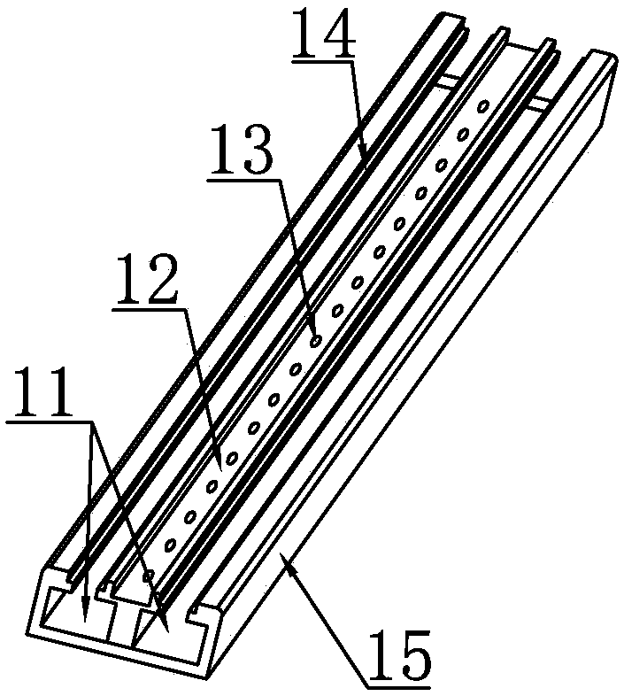
[0032] The shuttle air-floating guide rail of a shuttle loom provided in Embodiment 2 of the present invention is basically the same as Embodiment 1, the difference is that please refer to image 3 As shown, the air bearing guide rail 1 includes a guide rail base 15; the guide rail base 15 is a cuboid, and the middle part of the top end of the guide rail base 15 is provided with a first magnet placement groove 12 in the extension direction, and the first magnet is placed The two ends of the groove 12 communicate with the outside world. The bottom of the first magnet placement groove 12 is provided with a number of first threaded blind holes 13; There are two symmetrical ceramic placement grooves 14 , the two ends of the ceramic placement grooves 14 communicate with the outside world; the ceramic placement grooves 14 communicate with the compressed air flow groove 11 .

[0033] Furthermore, for a better connection of the permanent magnets to the rail base and the shuttle, see ...

Embodiment 3

[0035] The shuttle air-floating guide rail of a shuttle loom provided in Embodiment 3 of the present invention is basically the same as Embodiment 2, the difference is that please refer to Figure 6 As shown, in order to achieve a better suspension effect of the shuttle, the plug 2 is a cuboid plate; the top of the plug 2 has a gap 22, and the width of the gap 22 is the same as the width of the first permanent magnet 4 ; Two second through holes 21 are arranged horizontally side by side on the plug 2 .


PUM


Abstract

The invention discloses a shuttle air draft guide rail of a shuttle loom, comprising an air draft guide rail and a shuttle suspended above the air draft guide rail, wherein a plurality of first permanent magnets and a plurality of porous ceramics arranged at two sides of the first permanent magnets are arranged at the top of the air draft guide rail along a length direction, and the plurality of porous ceramics at two sides are symmetric by taking the first permanent magnets as axis of symmetry; two compressed air flowing channels are formed in the air draft guide rail, the two compressed airflowing channels are respectively communicated with the plurality of porous ceramics at two sides; air compressors are connected to the outside of the compressed air flowing channels; plugs are respectively connected to two ends of the air draft guide rail; second permanent magnets mutually attracting with the first permanent magnets are connected to the bottom of the shuttle and air draft gaps exist between the air draft guide rail and the shuttle.

Description

technical field [0001] The invention belongs to the technical field of textile equipment, in particular to a shuttle air-floating guide rail of a shuttle loom. Background technique [0002] Textile machinery is the production means and material basis of the textile industry. Its technical level, quality and manufacturing cost are directly related to the development of the textile industry. The textile industry is an important advantageous industry in our country, the importance of its industrial upgrading is self-evident, and the progress of textile machinery design and manufacturing technology is the main content of the textile industry upgrading. Therefore, the technical innovation of the loom has a strong practical significance in the application field of textile machinery design and manufacture. The weft insertion device is the most important part of textile machinery, and its type is usually the basis for the classification of textile machinery. According to the weft ...

Claims


Application Information

Patent Timeline
Patent Type & Authority Applications(China)
IPC IPC(8): D03D49/42
CPCD03D49/42
Inventor 王广和张地
Owner 王广和
Why Eureka
Try Eureka