
Environmental protection monitoring device

A technology for environmental protection monitoring and equipment, applied in measuring devices, measuring electrical variables, measuring current/voltage, etc., can solve the problems of complicated voltage and current sampling methods, small installation space, wrong wiring, etc., and achieve simple voltage and current sampling methods , Easy installation and maintenance, small structure size

Inactive Publication Date: 2018-06-29
NANJING XINLIAN ELECTRONICS +1
View PDF7 Cites 7 Cited by
  • Summary
  • Abstract
  • Description
  • Claims
  • Application Information

AI Technical Summary

Problems solved by technology

[0006] Although the above-mentioned environmental protection monitoring equipment realizes the function of power collection, its voltage and current sampling methods are complicated, and the site not only needs to be connected to a current transformer or a Hall sensor, but also needs to be connected to a strong current through a wiring clip to be able to collect the cross-collection data. voltage, so as to realize the power harvesting function
In some installation conditions, due to the small installation space, it is easy to cause wiring confusion, wrong wiring, electric shock, short circuit protection and other problems

Method used


Image

  • Environmental protection monitoring device
  • Environmental protection monitoring device
  • Environmental protection monitoring device

Examples


Embodiment Construction

[0020] In order to make the purpose, technical solutions and advantages of the embodiments of the present invention more clear, the embodiments of the present invention will be further described in detail below in conjunction with the accompanying drawings. Here, the exemplary embodiments and descriptions of the present invention are used to explain the present invention, but not to limit the present invention.

[0021] The inventor conducted market research and combined with the actual needs of my country's current environmental protection management agencies, aiming at the characteristics that various types of pollution control facilities such as water pollution control equipment, air pollution control equipment, and noise and vibration control equipment need to use electric power to operate, combined with the long-term The technical advantages accumulated in the research and development of electric energy information collection and electric energy metering system products, co...


PUM


Abstract

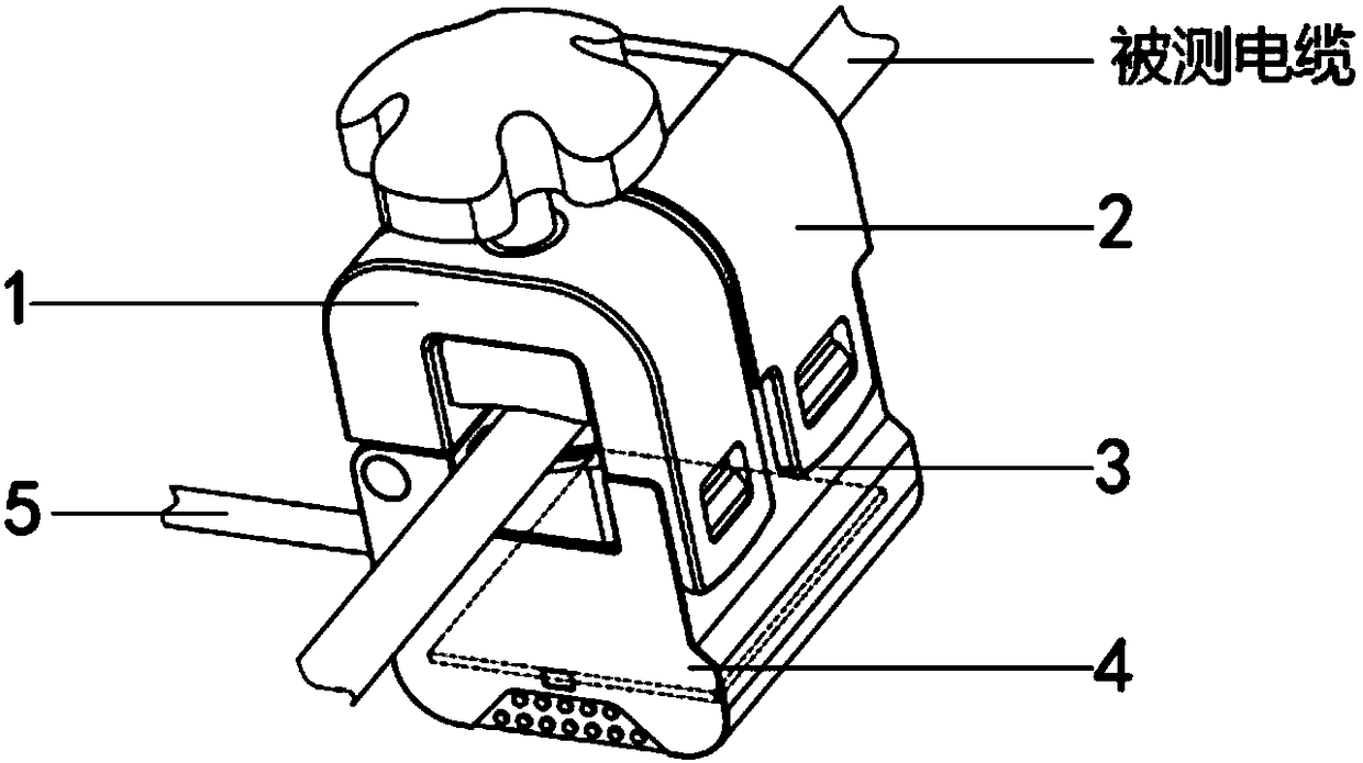
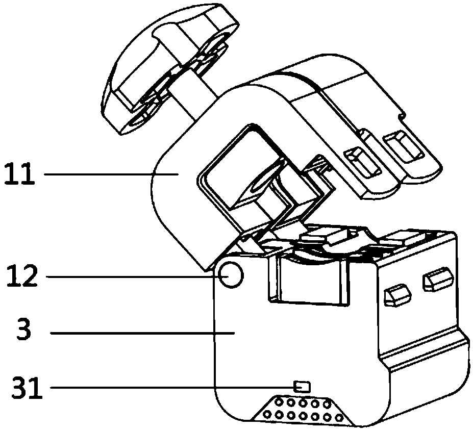
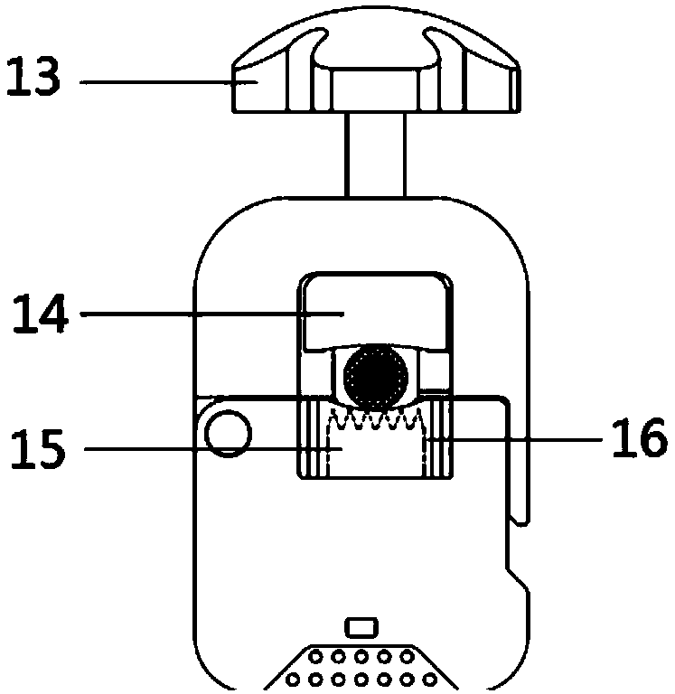
The invention discloses an environmental protection monitoring device, comprising a voltage sampling unit, a current sampling unit, a device base, a circuit functional unit, and power and signal cables, wherein the voltage sampling unit and the current sampling unit are connected to the device base; a cable under test is clamped in via an open structure; the circuit functional unit is mounted in the device base; the power and signal cables are connected inside; the voltage sampling unit is used for acquiring a voltage sample signal of the cable under test; the current sampling unit is used foracquiring a current sample signal of the cable under test; the circuit functional unit is used for processing the voltage sample signal and the current sample signal. The power and signal cables areused for providing access for power and transmitting signals. The voltage and current sampling modes of the environmental protection monitoring device can be simplified; the environmental protection monitoring device is convenient to install.

Description

technical field [0001] The invention relates to the technical field of environmental monitoring, in particular to environmental monitoring equipment. Background technique [0002] For environmental protection monitoring, the traditional solution is completed by using a current transformer. The current transformer is composed of a primary transformer and a secondary transformer (generally called an instrument transformer, installed in a collector), which is large in size and high in cost. Restricted installation is difficult, and even some branch circuits need to be modified to install; there are many branch circuits in the power consumption unit, and each circuit needs to be connected to current transformers, collectors, communication equipment and other equipment, and the equipment cost is high; The voltage signal is connected to the branch circuit, and a power outage operation is required during installation, which will affect the production and operation activities of the...

Claims


Application Information

Patent Timeline
IPC IPC(8): G01R19/00
CPCG01R19/00
Inventor 王万胜杨飞
Owner NANJING XINLIAN ELECTRONICS
Learn More