Mine storage battery electric locomotive mounted charging and driving integrated circuit structure

An on-board charging and circuit structure technology, applied in the fields of electric energy storage, power electronics and electric drive, can solve the problems of poor battery life, low charging quality and efficiency, long battery charging time, etc., to achieve the ability to improve dynamic power, improve charging and operating efficiency, the effect of solving the difficulty of starting with full load

Inactive Publication Date: 2018-06-29
ANHUI UNIV OF SCI & TECH
View PDF4 Cites 16 Cited by
  • Summary
  • Abstract
  • Description
  • Claims
  • Application Information

AI Technical Summary

Problems solved by technology

The charging time of the battery is long, the efficiency is low, and charging equipment must be installed, the initial investment is large, the efficiency of electricity consumption is low, and the transportation cost is high
In order to solve the problems of huge charging equipment, low charging quality efficiency, low energy efficiency conversion ratio, and poor battery life for mining battery electric locomotives, an integrated on-board charging and driving device is required to realize the integration of charging and discharging, reduce the use cost of electric locomotives, and improve work efficiency
[0003] Mining battery electric locomotive, due to the characteristics of the battery itself, is only suitable for constant current working mode. When the electric locomotive is started and accelerated, the battery is difficult to discharge with a large current instantaneously, so that the output torque of the driving motor is insufficient, and the high current discharge seriously affects the battery. life

Method used


Image

  • Mine storage battery electric locomotive mounted charging and driving integrated circuit structure
  • Mine storage battery electric locomotive mounted charging and driving integrated circuit structure
  • Mine storage battery electric locomotive mounted charging and driving integrated circuit structure

Examples


Embodiment Construction

[0026] The preferred embodiments of the present invention will be described in detail below in conjunction with the accompanying drawings, so that the advantages and features of the present invention can be more easily understood by those skilled in the art, so as to define the protection scope of the present invention more clearly.

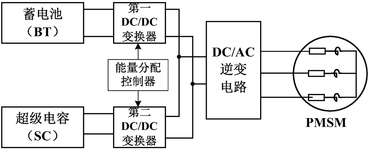
[0027] see figure 1 , the embodiment of the present invention includes:

[0028] An integrated circuit structure for on-board charging and driving of a mining battery electric locomotive, mainly including a battery, a super capacitor, a first DC-DC converter, a second DC-DC converter, an inverter circuit, a driving motor, and an energy distribution controller . One end of the first DC-DC converter is connected in series with the storage battery, and the other end is connected in parallel with the inverter circuit; one end of the second DC-DC converter is connected in series with the supercapacitor, and the other end is connected in parallel with...


PUM


Abstract

The invention discloses a mine storage battery electric locomotive mounted charging and driving integrated circuit structure. The structure mainly comprises a storage battery, a supercapacitor, a first DC-DC converter, a second DC-DC converter, an inverter circuit and a driving motor; one end of the first DC-DC converter is connected with the storage battery in series, the other end of the first DC-DC converter is connected with the inverter circuit in parallel, one end of the second DC-DC converter is connected with the supercapacitor in series, the other end of the second DC-DC converter isconnected with the inverter circuit in parallel, and the output end of the inverter circuit is connected with the driving motor in series. When a mine storage battery electric locomotive is in the traction driving state, the storage battery and the supercapacitor supply power to the electric locomotive; when the mine storage battery electric locomotive is in the parking charging mode, the drivingmotor and the inverter circuit form a charging circuit of the electric locomotive. The problem that mine storage battery electric locomotive offline charging equipment is huge and low in charging efficiency is solved, and the mine electric locomotive charging and operation efficiency can be improved.

Description

technical field [0001] The invention relates to the technical fields of power electronics, electric transmission, and electric energy storage, in particular to an on-board charging and driving integrated circuit structure of a mining battery electric locomotive. Background technique [0002] Traditional mining electric locomotives use lead-acid batteries to store energy. The charging of the batteries is generally carried out offline in the underground electric locomotive charging room. Each electric locomotive must be equipped with 2-3 sets of battery packs. The battery charging time is long and the efficiency is low. Charging equipment must be installed, the initial investment is large, the power consumption efficiency is low, and the transportation cost is high. In order to solve the problems of huge charging equipment, low charging quality efficiency, low energy efficiency conversion ratio, and poor battery life for mining battery electric locomotives, an integrated on-bo...

Claims


Application Information

Patent Timeline
Patent Type & Authority Applications(China)
IPC IPC(8): H02P27/08H02M7/797H02M3/158H02J7/10B60L11/18
CPCB60L53/24H02J7/022H02J7/0068H02J7/06H02J7/345H02M3/158H02M7/797H02P27/08H02J7/00711Y02T10/64Y02T10/70Y02T10/7072Y02T10/72Y02T10/92Y02T90/14
Inventor 祝龙记杨金鑫黄琦王琦
Owner ANHUI UNIV OF SCI & TECH
Why Eureka
Try Eureka