Scoliosis screw-rod correction stent system

A scoliosis and stent system technology, applied in the field of orthopedic surgical medical devices, can solve problems such as distraction failure, high infection rate, and upper screw pullout

Active Publication Date: 2018-07-03
贺新宁
View PDF6 Cites 2 Cited by
  • Summary
  • Abstract
  • Description
  • Claims
  • Application Information

AI Technical Summary

Problems solved by technology

The clinical efficacy of spinal fusion technology in the treatment of scoliosis in mature populations is satisfactory, but in the treatment of scoliosis in growing children, there will be many problems and failures. "Phenomenon
In addition, premature fusion results in short upper body and affects the development of heart and lung functions, which is also unacceptable
The double-rod growing rod technology, which is still being promoted and applied in China, was once considered a good method, but its shortcomings have been reported at home and abroad in recent years: (1) Repeated operations are required (every 6 months on average); (2) Rod breakage Decoupling (or pulling out of the upper screw); (3) kyphotic deformity after the upper junction; (4) distraction failure; (5) complications such as spontaneous fusion are common; (6) higher infection rate, etc.
(3) The existing corrective devices at home and abroad cannot provide sufficient corrective stress on the top vertebra of the scoliosis
Its advantage is that it can avoid repeated surgical trauma to children, but it also has all the disadvantages of double-rod growth rods. It also cannot correct the lateral curvature immediately, and it is prone to nail

Method used


Image

  • Scoliosis screw-rod correction stent system
  • Scoliosis screw-rod correction stent system
  • Scoliosis screw-rod correction stent system

Examples


Embodiment Construction

[0098] The present invention will be described in further detail below in conjunction with the accompanying drawings and specific embodiments.

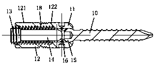
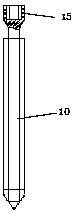
[0099] The scoliosis screw-rod correction bracket system of this embodiment includes pedicle screw 1, longitudinal connecting rod 2, puncture cone 3, guide pin 4, expansion core 5, screw setting guide sleeve 6, nail setter 7, screwdriver 8. Guide wire 9, hollow flat file 100, hollow wire tap 200, screw plug holder 300, rod holder 400, torque-resistant socket wrench 500, stretch presser 600, incision tissue retractor 700, Nail tail pliers 800, combination screwdriver 900, ejector 1000, fixing frame 1100 and stick adjuster 1200, such as Figure 1 to Figure 5 As shown, the pedicle screw 1 includes a nail body 10, a nail seat 11, two breakable long arms 12, a screw plug 13 and a cap 19, the nail body 10 is connected with the nail seat 11, and the two breakable long arms 12 are oppositely Fixedly connected to the nail base 11 to form a U-...


PUM


Abstract

The invention relates to a scoliosis screw-rod correction stent system. The scoliosis screw-rod correction stent system comprises a pedicle screw, a longitudinal connecting stick, a puncture cone, a guide pin, a guide wire, an expansion core, a screw placement guiding sleeve, a hollow potance file, a hollow screw tap, a nail loading device, a rod holding device, a plug screw holding device, a screwdriver, an unfolding pressurizer, an incision tissue retractor and an anti-torque socket spanner, wherein the pedicle screw comprises a screw body, a screw seat, two long arms which can be broken, aplug screw and a cap, the two long arms which can be broken are connected with the nail seat to form a U-shaped structure, a concave incisura is formed in each long arm which can be broken, the concave incisurae can divide the long arms which can be broken into broken arms and short arms, an external screw thread is formed on the outer surface of the short arm of each long arm which can be broken,the cap is used for being sheathed at one end, close to the concave incisurae, of the short arms of the long arms which can be broken and is provided with an internal screw thread matched with the external screw threads of the short arms, and the cap is provided with a cap holding hole. The scoliosis screw-rod correction stent system provided by the invention is flexible, simple and rapid in operation, labor is saved, and accuracy, stability and reliability of an embedded screw-rod correction stent are high.

Description

technical field [0001] The invention relates to the technical field of orthopedic surgery medical instruments, in particular to a scoliosis screw rod correction support system. Background technique [0002] Scoliosis refers to the scoliosis and rotational deformity of the spine. It is divided into infantile type (0-3 years old), juvenile type (4-10 years old), and adolescent type (over 10 years old). It seriously affects the health and mental health. Adolescent patients with severe scoliosis can undergo orthopedic fusion surgery, which has relatively little impact on their spine development and cardiopulmonary development. With the growth of age, the development of childhood to adolescence is very serious spinal deformity, the operation is difficult, the trauma is large, and there are many complications. Children's spinal deformity is soft and easy to correct. For young children with scoliosis, orthopedic fusion surgery significantly affects the development of the child's...

Claims


Application Information

Patent Timeline
IPC IPC(8): A61B17/70
CPCA61B17/7013A61B17/7025A61B17/7074A61B2017/565
Inventor 贺新宁
Owner 贺新宁
Why Eureka
Try Eureka