Uranium enrichment plant tail gas HF treatment process

A technology for treating process and tail gas, applied in the field of uranium enrichment process, can solve problems such as unfavorable safety and environmental protection, high comprehensive cost, complicated process, etc., and achieve the effects of being beneficial to environmental protection, improving safety and environmental protection, and simplifying process

Active Publication Date: 2018-07-06
CHINA NAT NUCLEAR URANIUM ENRICHMENT
View PDF6 Cites 5 Cited by
  • Summary
  • Abstract
  • Description
  • Claims
  • Application Information

AI Technical Summary

Problems solved by technology

[0006] The technical problem to be solved in the present invention is: the existing uranium enrichment plant tail gas HF

Method used


Image

  • Uranium enrichment plant tail gas HF treatment process
  • Uranium enrichment plant tail gas HF treatment process

Examples


Example Embodiment

[0051] Example 1

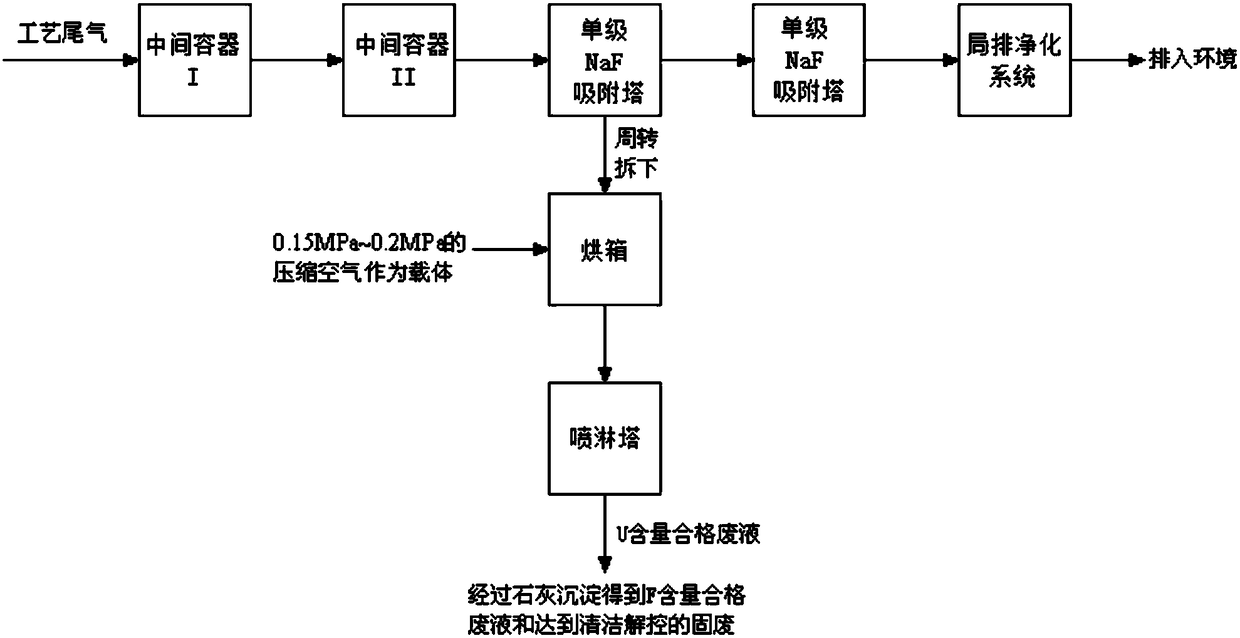
[0052] like figure 1 As shown, adopting the process of this embodiment to carry out HF treatment of feed material purification and concentrate purification system tail gas includes the following steps:

[0053] Step S1

[0054] The exhaust gas first enters the intermediate container I frozen in the refrigerator at about -80°C, and UF at -80°C 6 The saturated vapor pressure is 0.19Pa, so most of UF 6 Desublimation in the intermediate container I, UF ​​in the tail gas 6 The mass ratio to HF is reduced to around 10%.

[0055] In this embodiment, the pressure at the inlet of the intermediate container I is less than or equal to 800 Pa, and the opening of the valve at the outlet of the intermediate container I is 1 to 2 turns.

[0056] Step S2

[0057] The tail gas treated in step S1 enters the intermediate container II frozen in a refrigerator at about -90°C, and UF at -90°C 6 The saturated vapor pressure is 0.032Pa, and at this time UF 6 content has bee...

Example Embodiment

[0075] Example 2

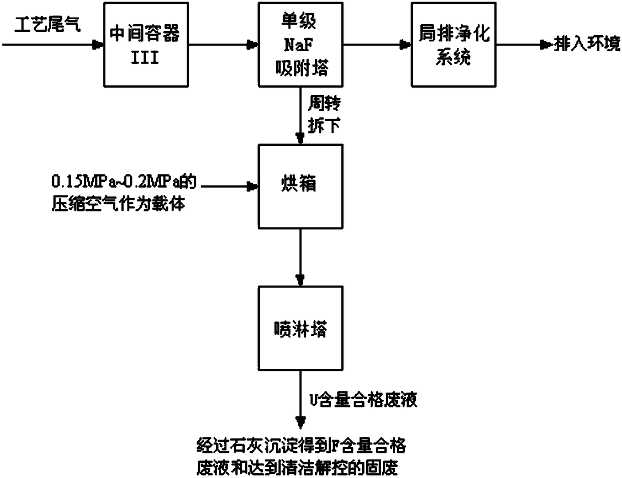
[0076] like figure 2 As shown, adopting the process of this embodiment to carry out purging and evacuating system tail gas HF treatment includes the following steps:

[0077] Step P1

[0078] The exhaust gas first enters the intermediate container III frozen in the refrigerator at about -80°C, and UF at -80°C 6 The saturated vapor pressure is 0.19Pa, after UF 6 Desublimation, UF in exhaust 6 The mass ratio to HF is reduced from about 10% to 0.00001 or even lower. This step can ensure that the U content in the tail gas is qualified.

[0079] In this embodiment, the pressure at the inlet of the intermediate container III is less than or equal to 800 Pa, and the opening of the valve at the outlet of the intermediate container III is 1 to 2 turns.

[0080] Step P2

[0081] The tail gas treated in step P1 enters the single-stage NaF adsorption tower, and HF reacts with NaF to produce NaHF 2 , thus being collected by adsorption.

[0082] In this example,...


PUM

PropertyMeasurementUnit
Effective diameteraaaaaaaaaa
Diameteraaaaaaaaaa
Diameteraaaaaaaaaa

Abstract

Belonging to the technical field of uranium enrichment technology, the invention in particular relates to a uranium enrichment plant tail gas HF treatment process. The uranium enrichment plant tail gas HF treatment process includes: employing refrigeration cabinet refrigerated intermediate containers, NaF adsorption towers and a local discharge purification system for purification treatment on tail gas HF, and discharging the tail gas into the environment when the tail gas is detected to be qualified; and conducting desorption treatment on the adsorption towers reaching an adsorbing capacity limit, and reacting the desorption treatment generated neutralizing waste liquid with lime to obtain waste liquid meeting the discharge standard and solid waste reaching the clearance level. The process provided by the invention solves the technical problems of complex procedure, high comprehensive cost and adverseness to safety and environmental protection, gets rid of the dependence of HF collection on liquid nitrogen, simplifies the process flow, reduces the comprehensive cost, and greatly improves the safety and environmental protection of the tail gas HF treatment process.

Description

technical field [0001] The invention belongs to the technical field of uranium enrichment process, and in particular relates to a HF treatment process for tail gas of a uranium enrichment plant. Background technique [0002] The tail gas produced by the feed purification, concentrate purification, purging and evacuation processes involved in the production of uranium enrichment plants includes UF 6 , HF, air / nitrogen, the UF in the exhaust gas must be 6 and HF are removed to make the tail gas meet the emission standard before it can be discharged. [0003] The tail gas contains more UF in the process of feed purification and concentrate purification 6 , UF 6 Total mass is more than HF total mass. UF in purge and evacuation process exhaust 6 content has been lowered, UF 6 The ratio of the total mass to the total mass of HF is about 5% to 15%. [0004] In the prior art, the following processes are used to collect HF: ①Use a single-stage -80°C refrigeration cabinet to co...

Claims


Application Information

Patent Timeline
IPC IPC(8): B01D53/68B01D53/96B01D53/82C01G43/06
CPCB01D53/002B01D53/685B01D53/96B01D2251/108B01D2251/304B01D2257/2047B01D2258/02C01G43/063
Inventor 张进荣吕永红杨小松王铁军关成明谢国和
Owner CHINA NAT NUCLEAR URANIUM ENRICHMENT
Why Eureka
Try Eureka