Density-distributed micro-chromatographic column chip and its manufacturing method

A technology of density distribution and manufacturing method, applied in the field of chromatographic analysis, can solve the problems of unfavorable, poor anti-interference ability, low resolution, etc.

Active Publication Date: 2021-04-09
INST OF ELECTRONICS CHINESE ACAD OF SCI
View PDF5 Cites 0 Cited by
  • Summary
  • Abstract
  • Description
  • Claims
  • Application Information

AI Technical Summary

Problems solved by technology

[0002] Aiming at the demand for rapid detection of pollutant gases in many fields such as ambient air quality monitoring, harmful gases released from building interiors and furniture, fixed-point pollution sources, and sudden environmental pollution, due to the complex background and various components of ambient gases, the detectors on the market Most of them have the weakness of poor anti-interference ability, and often need to use chromatographic technology to separate the mixed pollutant gas first, and then use various high-sensitivity detectors for detection, so as to solve the technical bottleneck of the poor resolution of the detector itself
[0003] Existing miniature chromatographic columns generally have cavity and semi-filled structures. The cavity structure has low resolution due to limited sample capacity.
Semi-filled structure, uniform arrayed columns are set in the chromatographic channel to increase the sample capacity, but due to the small width of the micro chromatographic channel, after the array column is set in the chromatographic channel, the gas resistance of the chromatographic channel increases suddenly , due to the structural principle, the gas resistance in the channel close to the gas inlet is small, and the gas resistance in the part closer to the gas outlet is larger. The combination of the above makes the flow rate and pressure distribution of the gas in the entire chromatographic channel very uneven, which in turn produces a very unfavorable Effect
During the coating process of the stationary phase, the inconsistency of the flow rate and pressure will cause the film thickness of the stationary phase in the chromatographic channel to be inconsistent, which is thinner near the inlet, and thicker as it is closer to the outlet, which leads to the separation of samples by the chromatographic column. Severe tailing of chromatographic peaks affects resolution and detection accuracy

Method used


Image

  • Density-distributed micro-chromatographic column chip and its manufacturing method
  • Density-distributed micro-chromatographic column chip and its manufacturing method

Examples


Embodiment Construction

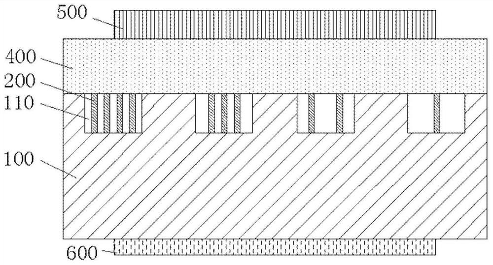
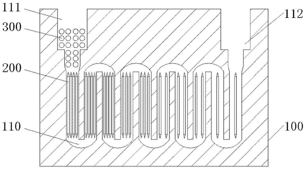
[0026] The present disclosure provides a density-distributed micro-chromatographic column chip and a manufacturing method thereof. Since the air resistance in the channel close to the inlet part is small, the closer to the outlet of the chromatographic column, the greater the gas resistance, and the flow rate of gas in the entire chromatographic channel and the pressure distribution is very uneven, so the disclosure improves the surface area and sample capacity of the chromatographic channel by changing the setting density of the column wall in the channel, and optimizes the flow velocity and pressure distribution in the chromatographic channel to make them tend to be consistent. It is conducive to the uniform coating of the stationary phase in the chromatographic channel, so as to realize the efficient separation of samples.

[0027] In order to make the purpose, technical solutions and advantages of the present disclosure clearer, the present disclosure will be further descri...


PUM

PropertyMeasurementUnit
widthaaaaaaaaaa
depthaaaaaaaaaa
widthaaaaaaaaaa

Abstract

The present disclosure provides a density-distributed micro-chromatographic column chip and a manufacturing method thereof. Since the air resistance in the channel close to the inlet part is small, the closer to the outlet of the chromatographic column, the greater the gas resistance, and the flow rate of gas in the entire chromatographic channel and the pressure distribution is very uneven, so the disclosure improves the surface area and sample capacity of the chromatographic channel by changing the setting density of the column wall in the channel, and optimizes the flow velocity and pressure distribution in the chromatographic channel to make them tend to be consistent. It is conducive to the uniform coating of the stationary phase in the chromatographic channel, so as to realize the efficient separation of samples.

Description

technical field [0001] The present disclosure relates to the technical field of chromatographic analysis, in particular to a density-distributed micro-chromatographic column chip and a manufacturing method thereof. Background technique [0002] Aiming at the demand for rapid detection of pollutant gases in many fields such as ambient air quality monitoring, harmful gases released from building interiors and furniture, fixed-point pollution sources, and sudden environmental pollution, due to the complex background and various components of ambient gases, the detectors on the market Most of them have the weakness of poor anti-interference ability, and often need to use chromatographic technology to separate the mixed polluted gas first, and then use various high-sensitivity detectors for detection, so as to solve the technical bottleneck of the poor resolution of the detector itself. [0003] Existing micro-chromatographic columns generally have cavity and semi-filled structur...

Claims


Application Information

Patent Timeline
Patent Type & Authority Patents(China)
IPC IPC(8): G01N30/02G01N30/60
CPCG01N30/02G01N30/606G01N30/6095
Inventor 孙建海薛宁刘春秀赵佩月
Owner INST OF ELECTRONICS CHINESE ACAD OF SCI
Why Eureka
Try Eureka