
Direct current bus voltage control system and control method thereof

A technology of DC bus voltage and DC voltage, applied in the direction of power transmission AC network, etc., can solve the problem that the DC control loop cannot accurately adjust the DC voltage, DC voltage fluctuations, etc., and achieve the effect of avoiding oscillation and system instability

Active Publication Date: 2018-07-06
BEIJING TIANYUAN SCI & TECH CREATION WINDPOWER TECH
View PDF6 Cites 0 Cited by
  • Summary
  • Abstract
  • Description
  • Claims
  • Application Information

AI Technical Summary

Problems solved by technology

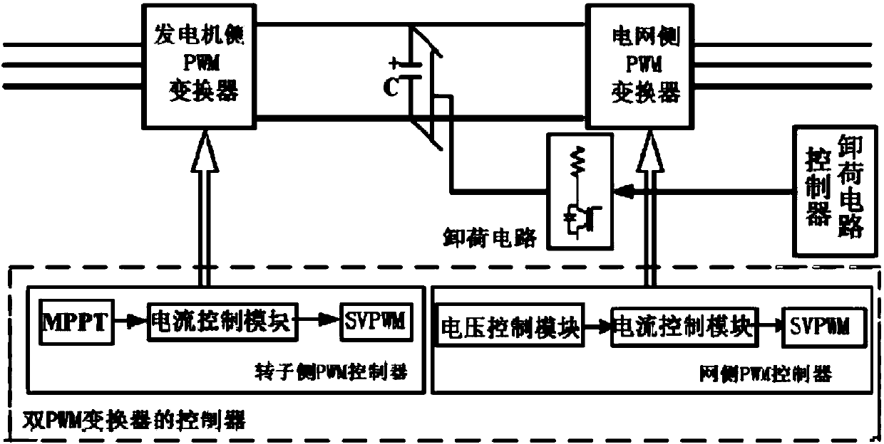
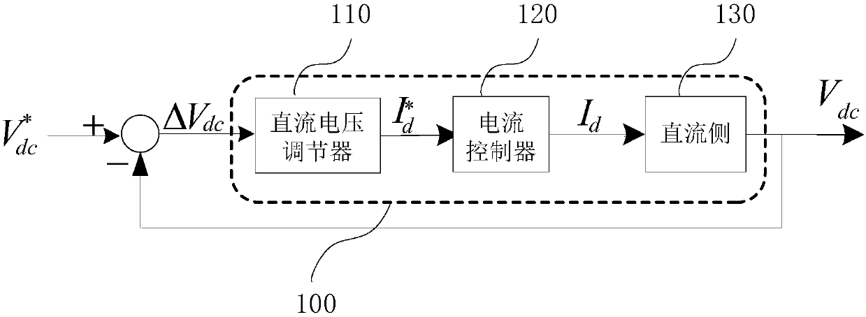
[0006] by figure 1 , figure 2 The control system structure shown is representative. In the existing DC bus voltage control strategy, the abnormal fluctuation of the bus voltage is controlled by a single voltage loop. In this control structure, when the DC bus voltage fluctuates, this This change exists as a disturbance to the entire control system
Moreover, since the DC control loop of the converter lacks a link that can reflect the influence of the unloading circuit on the DC voltage, the DC control loop cannot accurately adjust the DC voltage when the unloading circuit is working. During the dynamic process of DC voltage regulation, the unloading circuit Due to the fluctuation of the DC voltage, the power device will be switched on and off repeatedly, causing the DC voltage to fluctuate in a large range

Method used


Image

  • Direct current bus voltage control system and control method thereof
  • Direct current bus voltage control system and control method thereof
  • Direct current bus voltage control system and control method thereof

Examples


Embodiment Construction

[0035] Features and exemplary embodiments of various aspects of the invention will be described in detail below. In the following detailed description, numerous specific details are set forth in order to provide a thorough understanding of the present invention. It will be apparent, however, to one skilled in the art that the present invention may be practiced without some of these specific details. The following description of the embodiments is only to provide a better understanding of the present invention by showing examples of the present invention. The present invention is by no means limited to any specific configurations and algorithms presented below, but covers any modification, substitution and improvement of elements, components and algorithms without departing from the spirit of the invention. In the drawings and the following description, well-known structures and techniques have not been shown in order to avoid unnecessarily obscuring the present invention.

...


PUM


Abstract

The invention discloses a direct current bus voltage control system and a control method thereof, and relates to the field of wind power generation. The direct current bus voltage control system comprises a direct current voltage adjustment module, a current control module, a direct current side module and a brake state feedforward module which are connected in series in sequence; a direct currentside voltage V<dc> is multiplied with a brake state parameter D<c> and then is input into the brake state feedforward module; the output of the brake state feedforward module is used as a brake compensation current I<c>; the brake compensation current I<c> is fed into a current compensation node between the current control module and the direct current side module in a feedforward form to be subtracted from the output I<d> of the current control module and then to be input into the direct current side module; the brake state parameter D<c> is a dynamic parameter for representing the action state of the direct current side brake apparatus; and the brake state feedforward module is a calculation module for calculating a compensation current according to the brake state parameter D<c>. The problem of wide-range fluctuations of the direct current voltage in the dynamic voltage adjustment process is solved.

Description

technical field [0001] The invention relates to the field of wind power generation, in particular to a control system and a control method for a DC bus voltage. Background technique [0002] With the continuous improvement of wind power installed capacity, the proportion of wind power in the grid is increasing, and the interaction between the grid-connected wind power system and the grid is also increasing. The mutual influence between the two is reduced, and the wind power system is required to have a strong voltage ride-through capability. Taking the permanent magnet direct drive wind power generation system as an example, it is a good control method to realize the voltage matching between the machine side and the grid side of the wind power generation system by controlling the constant value control of the DC bus voltage. [0003] The prior art discloses a control scheme whose control system structure is as follows figure 1 shown. Among them, the wind power system adop...

Claims


Application Information

Patent Timeline
IPC IPC(8): H02J3/36
Inventor 张一博张国驹
Owner BEIJING TIANYUAN SCI & TECH CREATION WINDPOWER TECH
Learn More