Crane with two trolleys and telescopic cantilever beams capable of rotating at any angle

A technology of cantilever beam and arbitrary angle, which is applied in the direction of traveling bridge cranes, cranes, traveling mechanisms, etc., can solve the problems of inability to directly hand over goods in the next workshop, waste of manpower and material resources, and inconvenience, so as to avoid tipping, improve efficiency, Guaranteed safety effect

Inactive Publication Date: 2018-07-10
福州市鼓楼区奇韵通自动化设备有限公司
View PDF0 Cites 2 Cited by
  • Summary
  • Abstract
  • Description
  • Claims
  • Application Information

AI Technical Summary

Problems solved by technology

[0002] Existing bridge cranes are used in enterprise workshops. Some workshops are equipped with many machine tools for processing and production. Products and raw materials need to be transported to the next workshop or other departments in real time; the hooks of the cranes in the workshop are hung from the trolley. For hoisting goods, the trolley can only run back and forth along the double girders of the crane, and the crane can only run back and forth along the cart rails on the cross columns on both sides of the workshop, so that the range of goods that the crane hook can lift is within the distance between the two cart rails in the workshop. Within the plane surrounded by the two ends, when the goods at the edge of the plane need to be hoisted, the hook will be pulled obliquely, and the items farther away from this plane (such as outside the workshop door, outside the span) cannot be hoisted. At this time, it can only be transferred with the help of other transportation equipment. Usually, the car drives into the workshop to lift the goods under the hook. Go to the hook to hand over the goods, and some set up a special cantilever crane at the workshop door (or workshop aisle) to transfer and dispatch the goods outside the workshop, first hoist the goods into the place where the crane hook of the workshop can reach , and then the cargo is hoisted by the crane to other stations in the workshop. The existing bridge crane used in this working condition cannot directly transfer the cargo with the workshop next door, and must use other transportation equipment to schedule operations, which brings considerable inconvenience. It also wastes manpower and material resources

Method used


Image

  • Crane with two trolleys and telescopic cantilever beams capable of rotating at any angle
  • Crane with two trolleys and telescopic cantilever beams capable of rotating at any angle
  • Crane with two trolleys and telescopic cantilever beams capable of rotating at any angle

Examples


Embodiment approach

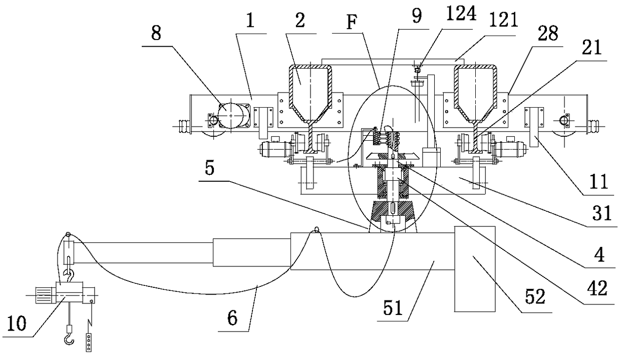
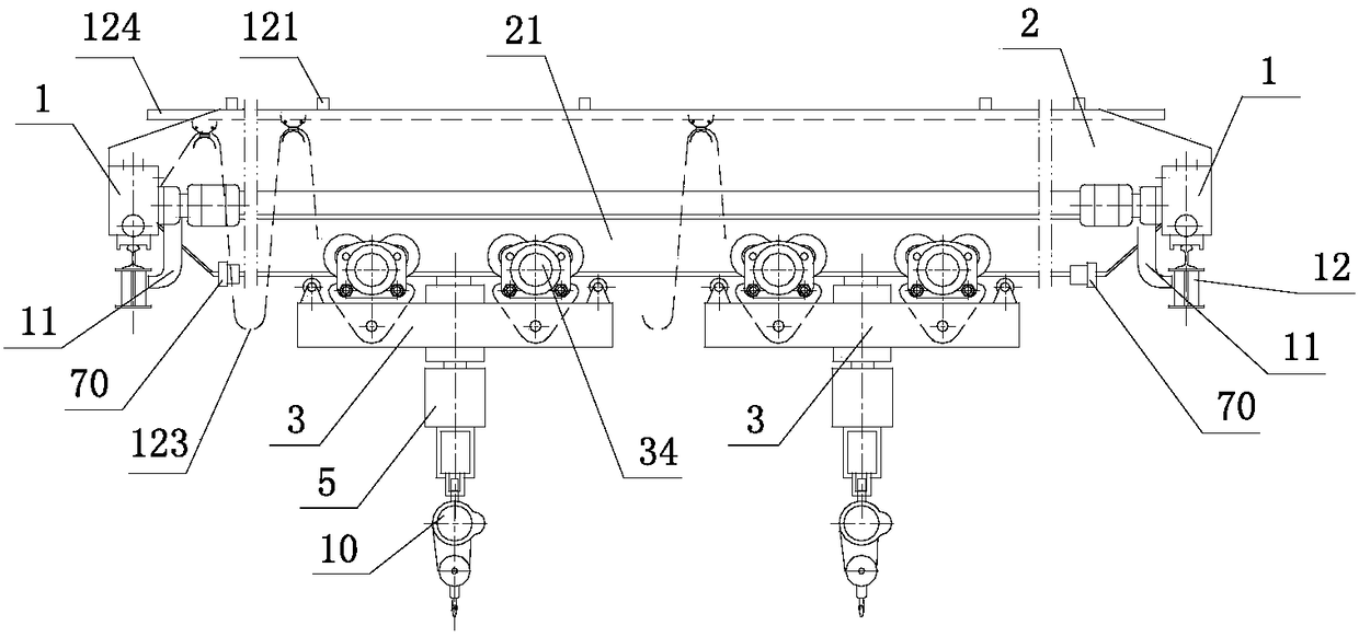
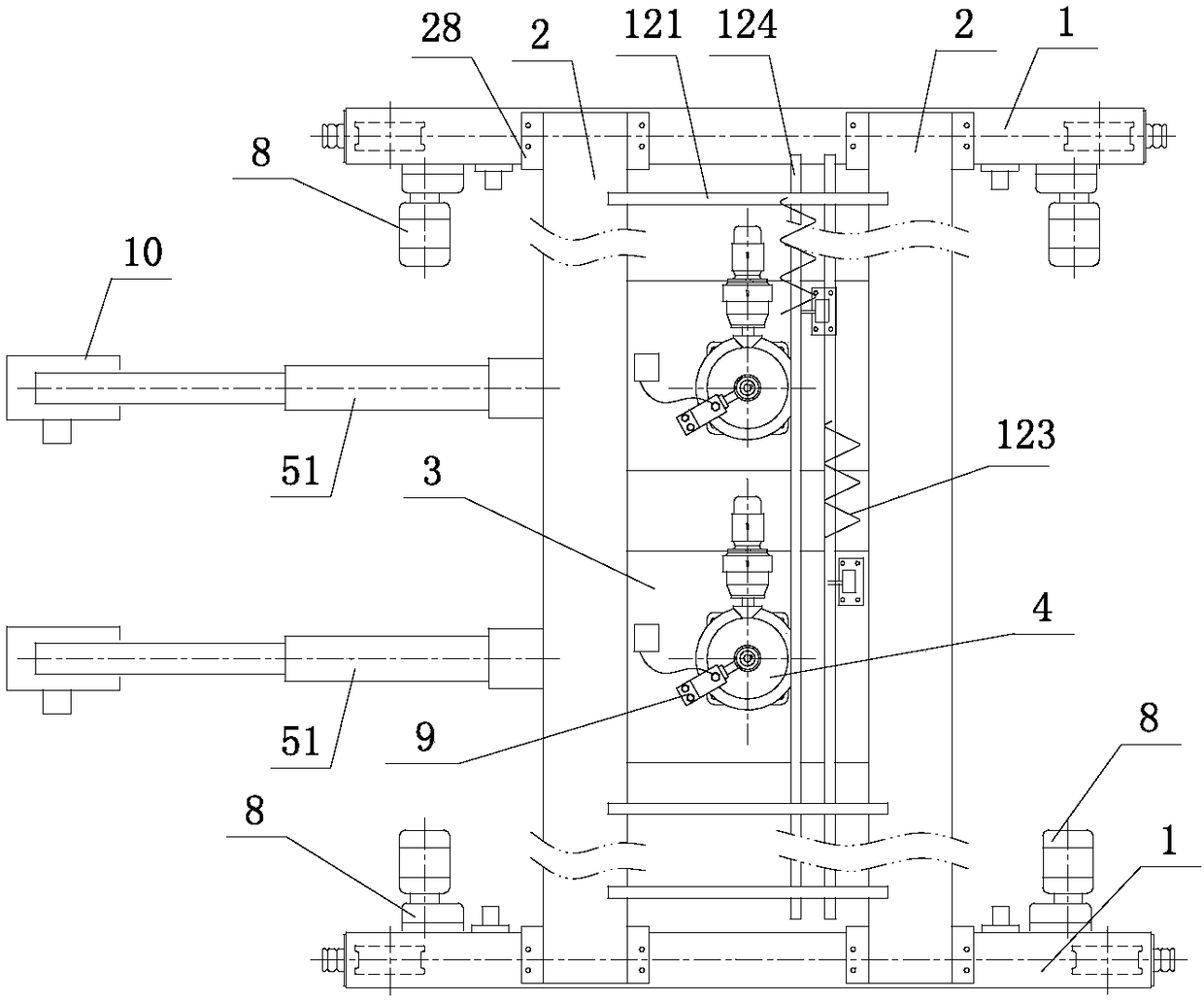
[0038] Such as figure 1 , figure 2 , image 3 As shown, a crane with two trolleys and a telescopic cantilever beam that can rotate at any angle includes a double-girder bridge frame 28; the double-girder bridge frame includes an end beam 1 and a main beam 2; it is characterized in that: the end beam 1 is two Both ends are provided with a cart driving device 8 with wheel teeth and a safety hook 11; the bottom of the main girder 2 is provided with an I-shaped steel track 21; Two operable suspension trolleys 3 are connected on the track 21; the suspension trolley is provided with a rotating mechanism 4 with fan gear transmission; the lower end of the boom shaft 42 in the rotating mechanism is connected with the cantilever member 5, and the upper end Connect the collector slip ring 9; the cantilever beam 51 in the cantilever member 5 is a telescopic beam; the telescopic movement of the cantilever beam is controlled by a hydraulic cylinder; one end of the cantilever beam is conn...


PUM


Abstract

The invention discloses a crane with two trolleys and telescopic cantilever beams capable of rotating at any angle. The crane comprises a double-beam crane span structure with end beams and main beams; the two ends of each end beam are both provided with cart driving devices and safe hooks; tracks at the lower portions of main beams are connected with two suspended trolleys; the suspended trolleysare provided with rotating mechanisms driving fan gears to rotate; the lower ends of suspension bar shafts in the rotating mechanism are connected with cantilever components, and the upper ends of the suspension bar shafts are connected with electricity collection sliding rings; the cantilever beams in the cantilever components are telescopic beams; the telescopic movement of the cantilever beamsis controlled by hydraulic cylinders; one end of each cantilever beam is connected with a hydraulic pressure station, and the other end of the corresponding cantilever beam is fixedly connected withan electric block; the cantilever beams are located at the lower portions of the main beams and can stretch out of a workshop to work, and can rotate at any angle in a horizontal plane.

Description

technical field [0001] The present application relates to the field of cranes, in particular to a crane with two trolleys and a telescopic cantilever beam capable of rotating at any angle. Background technique [0002] Existing bridge cranes are used in enterprise workshops. Some workshops are equipped with many machine tools for processing and production. Products and raw materials need to be transported to the next workshop or other departments in real time; the hooks of the cranes in the workshop are hung from the trolley. For hoisting goods, the trolley can only run back and forth along the double girders of the crane, and the crane can only run back and forth along the cart rails on the cross columns on both sides of the workshop, so that the range of goods that the crane hook can lift is within the distance between the two cart rails in the workshop. Within the plane surrounded by the two ends, when the goods at the edge of the plane need to be hoisted, the hook will b...

Claims


Application Information

Patent Timeline
Patent Type & Authority Applications(China)
IPC IPC(8): B66C17/04B66C11/16B66C9/00B66C13/12B66C6/00B66C7/00
CPCB66C17/04B66C6/00B66C7/00B66C9/00B66C11/16B66C13/12
Inventor 卢统华
Owner 福州市鼓楼区奇韵通自动化设备有限公司
Why Eureka
Try Eureka