Buoyancy platform displacement adjusting mechanism for sewage tank closure

A buoyancy platform and displacement adjustment technology, applied in sewage wells, motor vehicles, water supply devices, etc., can solve the problems of reducing the welding accuracy of two adjacent rolls of HDPE anti-seepage membrane, inaccurate adjustment of HDPE anti-seepage membrane, and failure of sealing performance. , to achieve the effect of improving laying efficiency, reducing labor intensity and prolonging service life

Active Publication Date: 2018-07-10
江苏康姆罗拉特种陶瓷有限公司
View PDF4 Cites 0 Cited by
  • Summary
  • Abstract
  • Description
  • Claims
  • Application Information

AI Technical Summary

Problems solved by technology

Covering the sewage pool with HDPE anti-seepage membrane can ensure that the sealing effect of the sewage pool meets the requirements, but because the construction volume of the general sewage pool is more than 4,000 cubic meters, and the exposed area of ​​the sewage pool is usually more than 1,000 square meters , in this regard, when using HDPE anti-seepage membrane to lay the opening of the sewage pool, it is necessary to use the HDPE anti-seepage membrane in rolls, and because the weight of the HDPE anti-seepage membrane in rolls is too large, a buoyancy platform needs to be set up in the sewage pool , to facilitate the laying of workers; but when welding between two adjacent rolls of HDPE anti-seepage membrane, it is necessary to continuously adjust the position of the two rolled HDPE anti-seepage membranes to ensure seamless welding between the two , and due to the large volume of the sewage tank, the area occupied by the buoyancy platform on the water surface is the same as the area of ​​a roll of HDPE anti-seepage membrane on the water surface, that is, when the buoyancy platform is pulled, once the local force on the buoyancy platform is uneven, It will easily lead to inaccurate position adjustment of the HDPE anti-seepage film, which will directly reduce the welding accuracy of two adjacent rolls of HDPE anti-seepage film, making the sealing performance composed of HDPE anti-seepage film invalid

Method used


Image

  • Buoyancy platform displacement adjusting mechanism for sewage tank closure
  • Buoyancy platform displacement adjusting mechanism for sewage tank closure
  • Buoyancy platform displacement adjusting mechanism for sewage tank closure

Examples


Embodiment 1

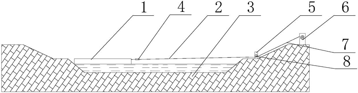
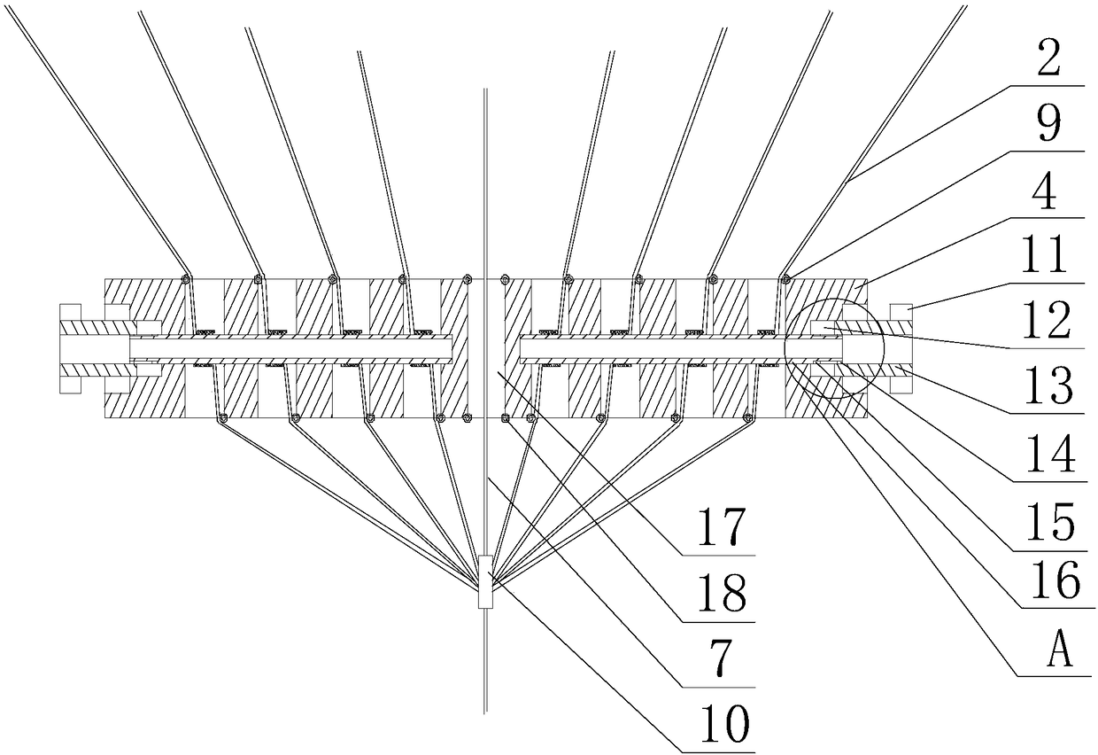
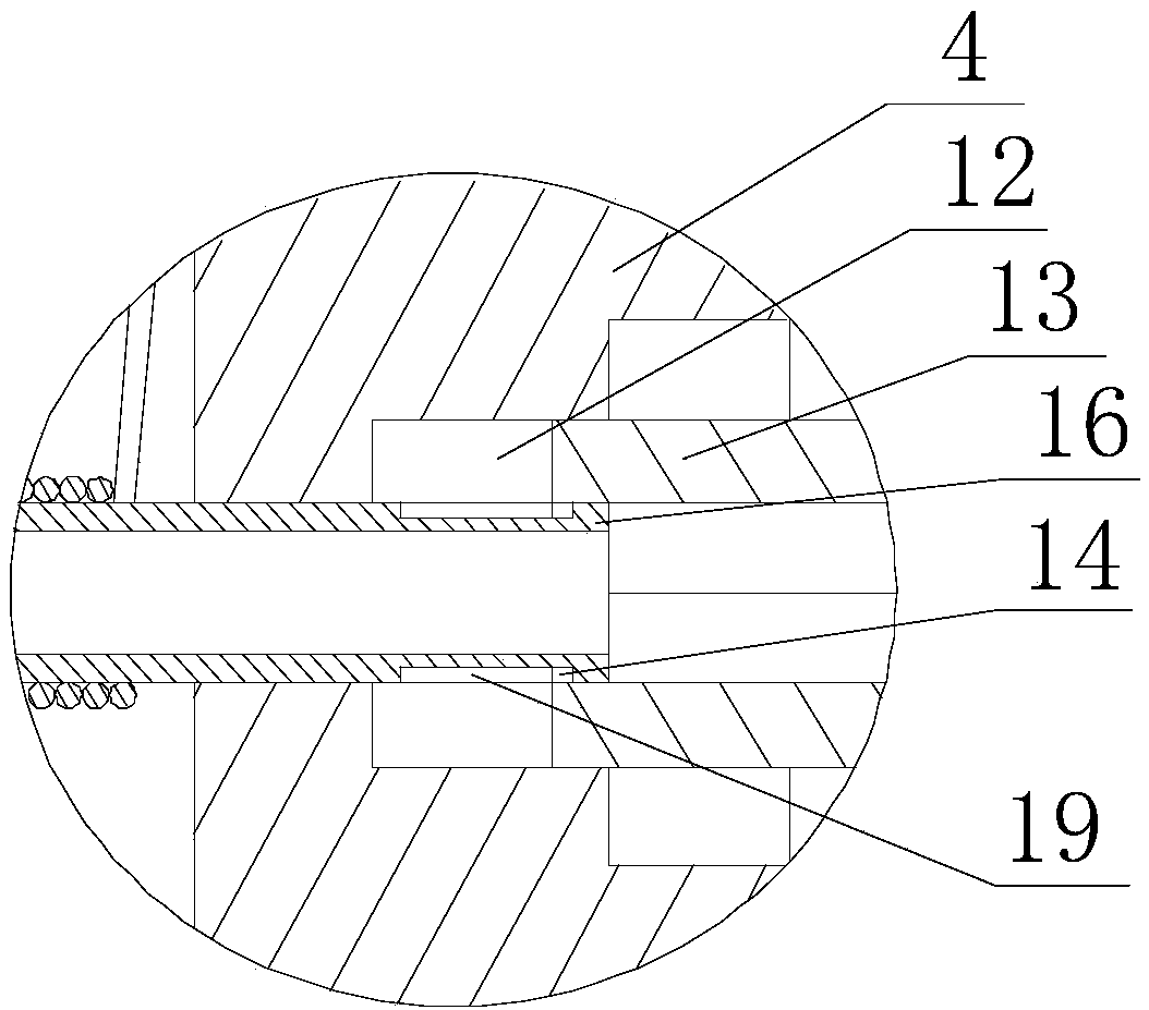
[0028] like Figure 1~3 as well as Figure 5 As shown, the present embodiment includes a hoist 6, a traction rope, a rectangular traction block 4 and a steering column 5, on which the steering column 5 is rotated and provided with a reversing wheel 8, and the traction rope is connected with the reversing wheel 8 after passing around the reversing wheel 8. The output end of the winch 6 is connected, and a plurality of parallel holes with axes parallel to each other are arranged on the traction block 4. Limiting grooves 12 are opened at both ends of the traction block 4, and the axes of the limiting grooves 12 are in line with the The axis of the wire-passing hole is vertical, and a rotating shaft 16 is arranged on the groove wall of each limiting groove 12, and the ends of the rotating shaft 16 move sequentially through the limiting groove 12 and the plurality of holes along the direction that the end of the traction block 4 points to its center. A wire hole, also includes a h...

Embodiment 2

[0034] like Figure 1~3 As shown, in this embodiment, a through hole 17 with an axis parallel to the wire passing hole is opened in the middle of the traction block 4 , and the main pull rope 7 is connected to the clamp 10 after moving through the small hole. Further, a through hole 17 is set in the middle part of the traction block 4 to facilitate the passing of the main stay rope 7, and one end of the main stay rope 7 is connected with the middle part of the buoyancy platform 1, and the other end is connected with the clamp 10. Driven by the drive, the length of the main stay rope 7 remains unchanged, that is, when adjusting, the buoyancy platform 1 will take the main stay rope 7 as the center, and the forward and reverse rotation of the two rotating shafts 16 will make them respectively located on both sides of the buoyancy platform 1. The lengths of the side stay ropes 2 are different, and the increase and decrease of the lengths of the side stay ropes 2 on the same side r...

Embodiment 3

[0037] like Figure 1~4 As shown, the wire passing hole in this embodiment includes a straight section 21 and a narrowing section 20 respectively connected to both ends of the straight section 21, and the inner diameter of the narrowing section 20 along the axis of the straight section 21 is Decreases from inside to outside, and two adjustment wheels 9 are respectively arranged on the side walls of the two narrowing sections 20 . Further, the wire passing hole includes two narrowed sections 20 and a straight section 21, so that a plurality of cavities with a large middle and small ends are formed in the traction block 4, and once the side pull rope 2 swings during the traction process, , the two small ports of the wire hole will directly limit the side stay rope 2, that is, the acting stress generated by quickly blocking the swing of the side stay rope 2 continues to be transmitted, and the local stay rope 2 inside the straight section 21 The section also has a certain space ...


PUM


Abstract

The invention discloses a buoyancy platform displacement adjusting mechanism for sewage tank closure. The mechanism comprises a winch, a pull rope, a pull block and a steering column, wherein a bend wheel is rotationally arranged on the steering column, multiple wire passing holes are formed in the pull block, limiting grooves are formed in two ends of the pull block, a rotating shaft is arrangedon the wall of each limiting groove, ends of the rotating shafts sequentially and movably penetrate through the limiting grooves and the multiple wire passing holes in the direction pointing to the center of the pull block from the end of the pull block, clamping grooves are formed in the walls of the limiting grooves, a clamping block is arranged on the outer circumferential wall of a limiting barrel, sliding chutes are formed in the outer circumferential walls of the rotating shafts, annular grooves are formed in outer circumferential walls of outer side ends of the rotating shafts in the circumferential direction of the rotating shafts, and a slider is arranged on the inner circumferential wall of the limiting barrel. The position of a buoyancy platform can be finely adjusted accordingto the welding progress of HDPE impermeable membranes on the premise that stable movement of the buoyancy platform is guaranteed, and the condition that the welding requirement cannot be met due to too large difference between overlapping areas of adjacent two rolls of HDPE impermeable membranes can be prevented.

Description

technical field [0001] The invention relates to the field of sewage treatment, in particular to a buoyancy platform displacement adjustment mechanism for sewage pool closure. Background technique [0002] Urban sewage is a general term for sewage discharged into urban sewage systems. In combined sewer systems, production wastewater and retained stormwater are also included. Urban sewage mainly includes domestic sewage and industrial sewage, collected by the urban drainage pipe network and transported to sewage treatment plants for treatment. Since the daily treatment capacity of the sewage treatment plant is limited, and the speed of sewage production is greater than the speed of sewage treatment, it is necessary to repair a special pool for the temporary storage of sewage beyond the capacity limit of the sewage treatment plant; but in the temporary storage During this period, due to the chemical reaction of the sewage after being exposed to the sun or in contact with the ...

Claims


Application Information

Patent Timeline
Patent Type & Authority Applications(China)
IPC IPC(8): E03F11/00B63B35/00
CPCB63B35/00E03F11/00
Inventor 杨蒙蒙
Owner 江苏康姆罗拉特种陶瓷有限公司
Why Eureka
Try Eureka