
A thermal cracking treatment device and method for high-moisture garbage

A treatment device and treatment method technology, applied in the direction of combustion method, lighting and heating equipment, combustion type, etc., can solve the problems of inability to continue the thermal cracking internal circulation of the gasifier, waste of gas combustion heat energy, and affect the sealing of the furnace body, etc. Achieve the effect of environmental protection, clean tail gas and maintain thermal cracking

Active Publication Date: 2019-06-11
深圳前海中惠能环保技术有限公司
View PDF6 Cites 0 Cited by
  • Summary
  • Abstract
  • Description
  • Claims
  • Application Information

AI Technical Summary

Problems solved by technology

In the above scheme, although the furnace body is filled with garbage and then sealed to ensure the sealing state during the thermal cracking process of the garbage, the garbage cannot be filled successively. With the thermal cracking of the garbage in the gasifier, the garbage in the furnace decreases and sinks continuously, and the upper part of the furnace It is in a hollow state, which causes waste of heat energy generated by the combustion of gas later, and cannot continue the internal circulation of thermal cracking in the gasifier; if the continuous feeding is easy to affect the sealing of the furnace body, it cannot meet the requirements of anaerobic or anoxic in the waste treatment process. Condition

Method used


Image

  • A thermal cracking treatment device and method for high-moisture garbage
  • A thermal cracking treatment device and method for high-moisture garbage
  • A thermal cracking treatment device and method for high-moisture garbage

Examples


Embodiment Construction

[0053] The present invention will be described in detail below with reference to the accompanying drawings and embodiments.

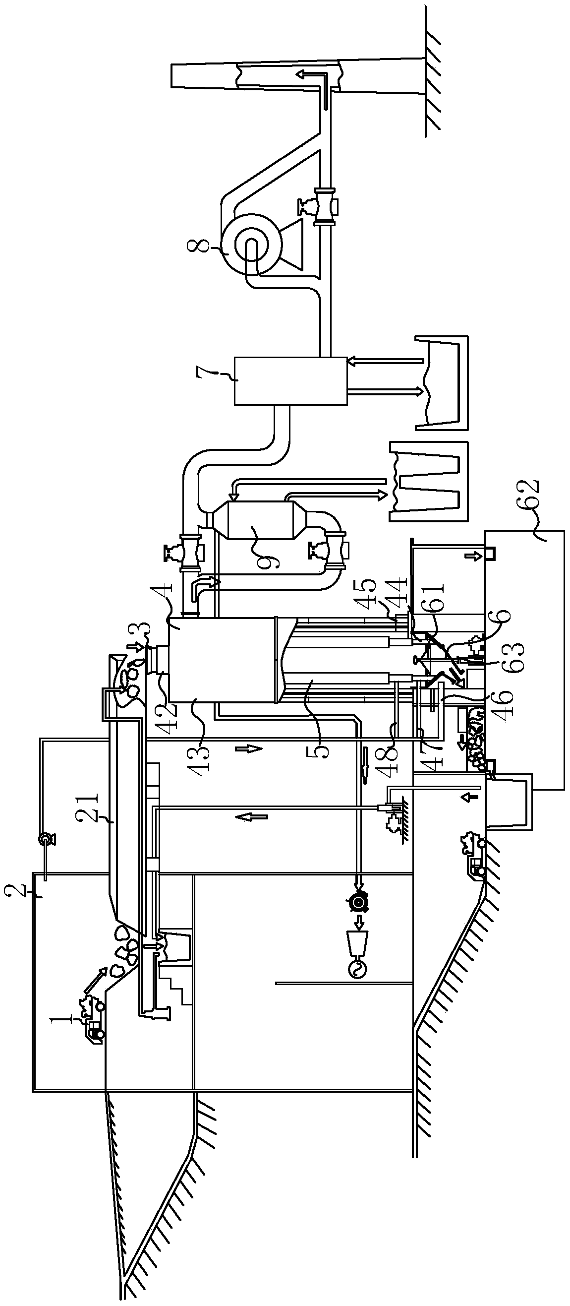
[0054] A high-moisture waste thermal cracking treatment device, such as figure 1 As shown, it includes a garbage truck 1 for transporting garbage, a sealed garbage bin 2 for storing garbage and a conveying device 21 for conveying garbage;

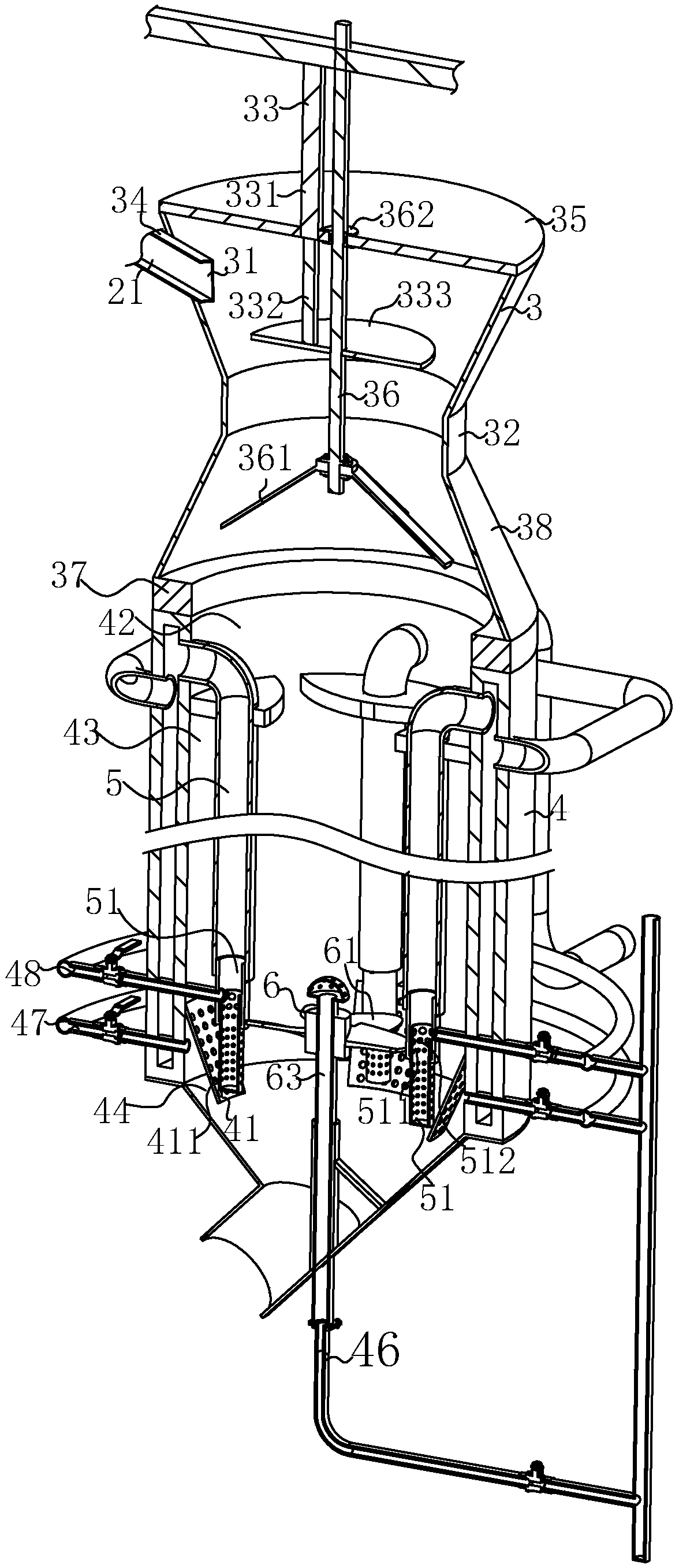
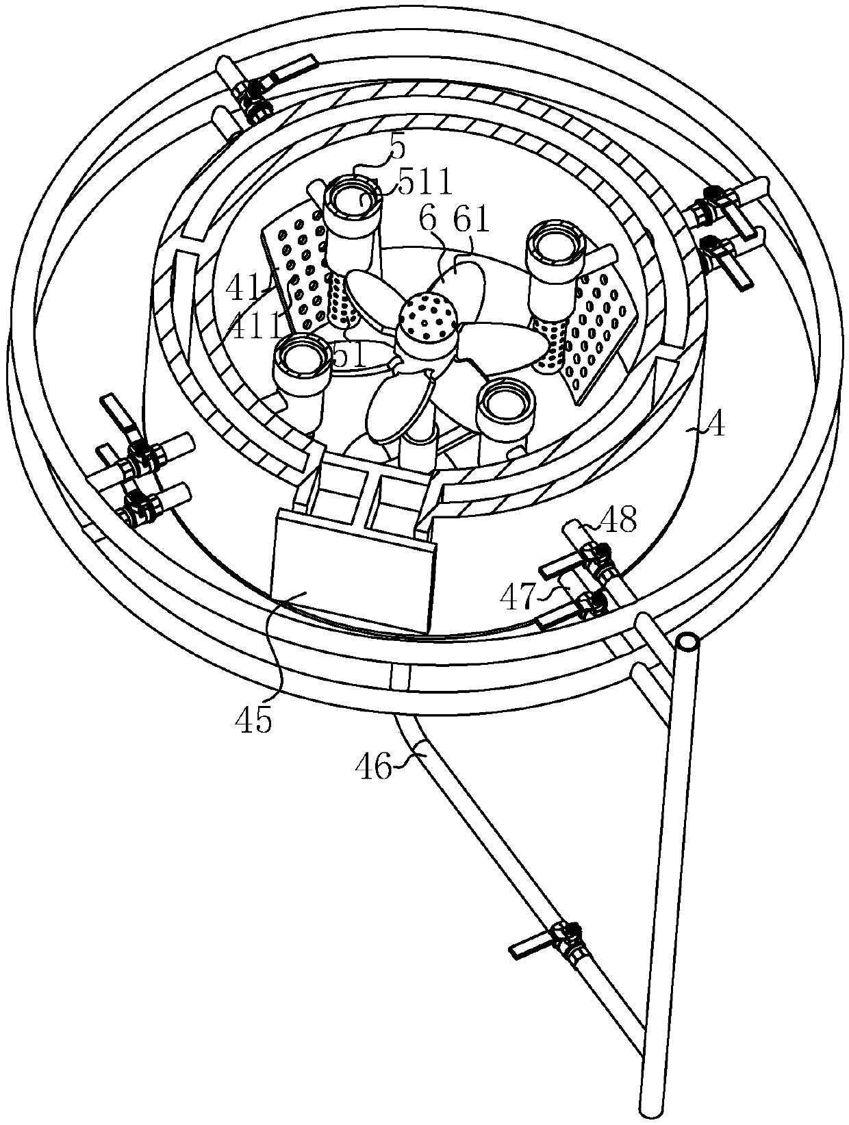
[0055] like figure 1 and figure 2 As shown, the high-moisture waste thermal cracking treatment device also includes a pyrolysis furnace 4 installed at the end of the conveying device 21 to process waste, and a gasket 37 made of ceramics with low thermal conductivity is installed on the top of the pyrolysis furnace 4. The gasket 37 is installed with The double cone-shaped pre-feeding device 3 for throwing and pre-storing garbage, a feeding port 42 is opened between the pre-feeding device 3 and the pyrolysis furnace 4, the upper part of the pre-feeding device 3 is set in a conical shape, and the upper part of the pr...


PUM


Abstract

The invention discloses a high-moisture garbage thermal cracking treatment device and method, and aims to solve the problem of incapability of giving consideration to continuous feeding and sealing ofa feed port of a furnace body. The device comprises a thermal cracking furnace; a prefeeding device is arranged at the top of the thermal cracking furnace; a filling hole for enabling garbage to fallinto a feed port of the thermal cracking furnace and a feeding port for pouring the garbage into the prefeeding device are arranged at the bottom of the prefeeding device; the end, near the thermal cracking furnace, of the prefeeding device extends in a direction perpendicular to the ground to form a prestorage part; and an opening in the connected place of the prefeeding device with the prestorage part is larger than or as large as an opening of the prestorage part. The device further comprises an auxiliary feeding device for enabling the garbage, blocked in the prestorage part, to enter thethermal cracking furnace. The device has the characteristic of natural sealing of the thermal cracking furnace at the time of realizing continuous feeding, and increases the utilization rate of heatenergy generated by gas combustion; and the thermal cracking furnace further meets anaerobic or anoxic conditions needed by thermal cracking of the garbage in the furnace body through natural sealingof the garbage, so that the thermal cracking internal cycle in the thermal cracking furnace is maintained.

Description

technical field [0001] The invention relates to the field of garbage disposal, and more particularly, to a device and method for thermal cracking of high-moisture garbage. Background technique [0002] Energy saving and environmental protection, as the hot and difficult pursuit of today's era, have attracted the attention of all walks of life, and have also become the goals that all walks of life are striving for, among which the demand for garbage disposal is particularly prominent. [0003] Since the first half of China's "Eleventh Five-Year Plan" (2000--2005), the introduction of environmental protection technologies and market exploration, and the second half of the environmental protection market has officially emerged; during the "Twelfth Five-Year Plan" (2006--2010) period, the conventional Treatment of pollution sources such as solid waste and sewage) hotspots in first- and second-tier large and medium-sized cities. Driven by the market, from mass introduction, dige...

Claims


Application Information

Patent Timeline
IPC IPC(8): F23G5/027F23G5/033F23G5/12F23G5/04F23G5/44
CPCF23G5/027F23G5/033F23G5/04F23G5/444F23G5/448F23G2201/101F23G2201/301F23G2201/80F23G2204/103F23G2205/14
Inventor 游衍勇冯清源刘鸿逵张明全谢志刚
Owner 深圳前海中惠能环保技术有限公司
Learn More