Pyrolyzation and desorption device for sludge

A sludge and hot gas technology, applied in pyrolysis sludge treatment, water/sludge/sewage treatment, sludge treatment through temperature control, etc., can solve the problems of expensive treatment chemicals, human health hazards, ecological environment damage, etc. , to achieve the effect of realizing resource utilization, improving heating effect and improving safety

Pending Publication Date: 2017-05-10
ZHE JIANG ECO ENVIRONMENTAL TECH CO LTD
View PDF9 Cites 18 Cited by
  • Summary
  • Abstract
  • Description
  • Claims
  • Application Information

AI Technical Summary

Problems solved by technology

During the circulation of oil-based mud, vibrating screen machines, desanders, desilters, centrifuges and other equipment will continuously produce a mixture of cuttings and mud with different particle sizes. The mineral oil content exceeds 20%, which belongs to special hazardous waste and enters The natural environment will lead to serious soil and groundwater pollution accidents, cause serious damage to the ecological environment, and directly cause harm to human health. Therefore, the development of a reasonable treatment technology for waste oil-based mud has become an urgent domestic problem.
[0003] At present, the mature technology in China is to adopt LRET technology, that is, mechanically separate oil-based drilling cuttings—heat—recover and recycle the desorption agent. The disadvantage is that the equipment investment is high and the treatment agent is expensive.
The equipment occupies a large area, and it is difficult to realize processing while drilling
[0004] At present, some oilfield companies use microbial treatment technology to treat oil-based cuttings, which is to use microbial bacteria to repair and improve the soil's arable function on oil-based cuttings, and use microorganisms to decompose petroleum hydrocarbons and other organic substances in oil-based cuttings , but the disadvantage of this method is that the processing time is long and it is not easy to achieve large-scale
For many years, there has been no technically and economically feasible "oil-based mud" treatment method and device in China

Method used


Image

  • Pyrolyzation and desorption device for sludge
  • Pyrolyzation and desorption device for sludge
  • Pyrolyzation and desorption device for sludge

Examples


Embodiment 1

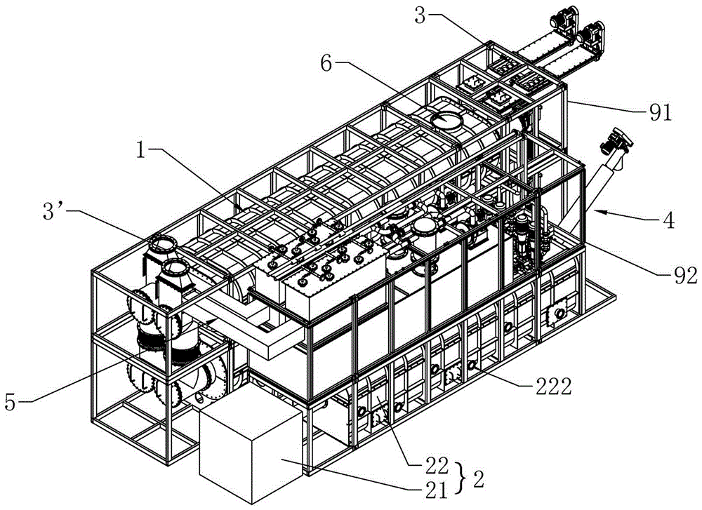
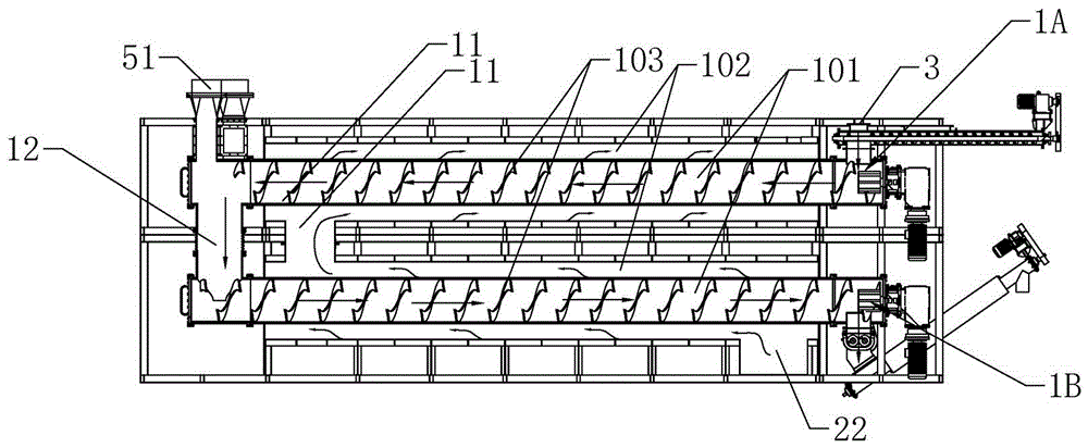
[0043] according to Figure 1 ~ Figure 3 Shown, a kind of sludge thermal desorption device, comprising:

[0044]The pyrolysis and desorption furnace body 1 is used for the pyrolysis and desorption of sludge and the transmission of sludge. The pyrolysis and desorption furnace body 1 is a nested structure of inner and outer chambers, including a pyrolysis and desorption chamber 101 for holding sludge and a coating In the heating chamber 102 outside the thermal desorption chamber 101, the thermal desorption chamber 101 is provided with a conveying mechanism 103, and the conveying mechanism 103 is a shaftless screw auger; the thermal desorption furnace body is divided into 1, and the upper furnace body 1A is arranged up and down. and the lower furnace body 1B, a hot gas ascending channel 11 is set between the upper furnace body 1A and the lower furnace body 1B to communicate with the heating chamber 102 of the two, and a material falling channel 12 is set between the upper furnace...

Embodiment 2

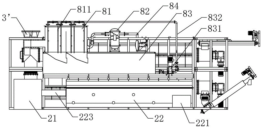
[0052] according to figure 1 As shown, the pyrolysis and desorption furnace body 1, the material inlet 3 and the material outlet 4 are arranged in the first skid 91, the hot gas generating device 2 and the tail gas processor 8 are arranged in the second skid 92, and the first skid 91 and The detachable connection between the second skids 92 .

Embodiment 3

[0054] The thermal desorption and desorption device also includes a gas generator as shown in the figure, the gas generator is a nitrogen generator or a superheated steam generator, and the gas outlet of the gas generator is directly connected with the thermal desorption chamber 101, and nitrogen or superheated steam is used as The protective gas directly heats the oily sludge in an oxygen-free or oxygen-deficient protective atmosphere.


PUM


Abstract

The invention relates to the field of sludge treatment, in particular to a pyrolyzation and desorption device for sludge. The pyrolyzation and desorption device comprises a pyrolyzation and desorption furnace body, a hot gas generating device, a material inlet, a material outlet, a mixed gas channel and a flue gas outlet; the pyrolyzation and desorption furnace body is used for pyrolyzation, desorption and transportation of the sludge; the pyrolyzation and desorption furnace body is of an inner cavity and outer cavity nested structure and comprises pyrolyzation and desorption cavities for holding the sludge and heating cavities coating the pyrolyzation and desorption cavities; a conveying mechanism is arranged in each pyrolyzation and desorption cavity; the pyrolyzation and desorption furnace body comprises an upper furnace body and a lower furnace body which are vertically arranged; a hot gas ascending channel is arranged between the upper furnace body and the lower furnace body and is used for making the heating cavity of the upper furnace body communicate with the heating cavity of the lower furnace body; a material falling channel is arranged between the upper furnace body and the lower furnace body and is used for making the pyrolyzation and desorption cavity of the upper furnace body communicate with the pyrolyzation and desorption cavity of the lower furnace body; the material inlet is formed in one end, away from the material falling channel, of the upper furnace body; the material outlet is formed in one end, away from the material falling channel, of the lower furnace body; the mixed gas channel is communicated with the pyrolyzation and desorption cavities.

Description

technical field [0001] The invention relates to the field of sludge treatment, in particular to a thermal desorption and desorption device for sludge. Background technique [0002] With the development of unconventional oil and gas such as shale gas and tight gas, the use of oil-based mud has gradually increased. Oil-based mud has the advantages of good rheological properties, fluid loss control performance and lubricity. However, during the drilling process, the treatment of the oil-based mud and cuttings mixture (referred to as oil-based cuttings) produced by the solids control circulation system has become a Huge environmental problem. During the circulation of oil-based mud, vibrating screen machines, desanders, desilters, centrifuges and other equipment will continuously produce a mixture of cuttings and mud with different particle sizes. The mineral oil content exceeds 20%, which belongs to special hazardous waste and enters The natural environment will lead to serio...

Claims


Application Information

Patent Timeline
Patent Type & Authority Applications(China)
IPC IPC(8): C10B53/00C10B51/00C02F11/10C02F11/18C02F103/36
CPCC10B51/00C10B53/00C02F11/10C02F2103/365Y02W10/40
Inventor 韩龙董博超
Owner ZHE JIANG ECO ENVIRONMENTAL TECH CO LTD
Why Eureka
Try Eureka