Heat pump heating system and heat pump heating method

A heating system and heat pump technology, which is applied in the field of heat pump heating systems and heat pump heating, can solve problems such as uneconomical use of energy, and achieve the effects of reducing operation difficulty, high comfort, and increasing heat exchange

Active Publication Date: 2018-07-10
QINGDAO HAIER NEW ENERGY ELECTRIC APPLIANCE +1
View PDF5 Cites 9 Cited by
  • Summary
  • Abstract
  • Description
  • Claims
  • Application Information

AI Technical Summary

Problems solved by technology

Although this method uses an expansion tank to reduce the number of times the heat pump is turned on, the principle used is to adjust t

Method used


Image

  • Heat pump heating system and heat pump heating method
  • Heat pump heating system and heat pump heating method

Examples


Embodiment 1

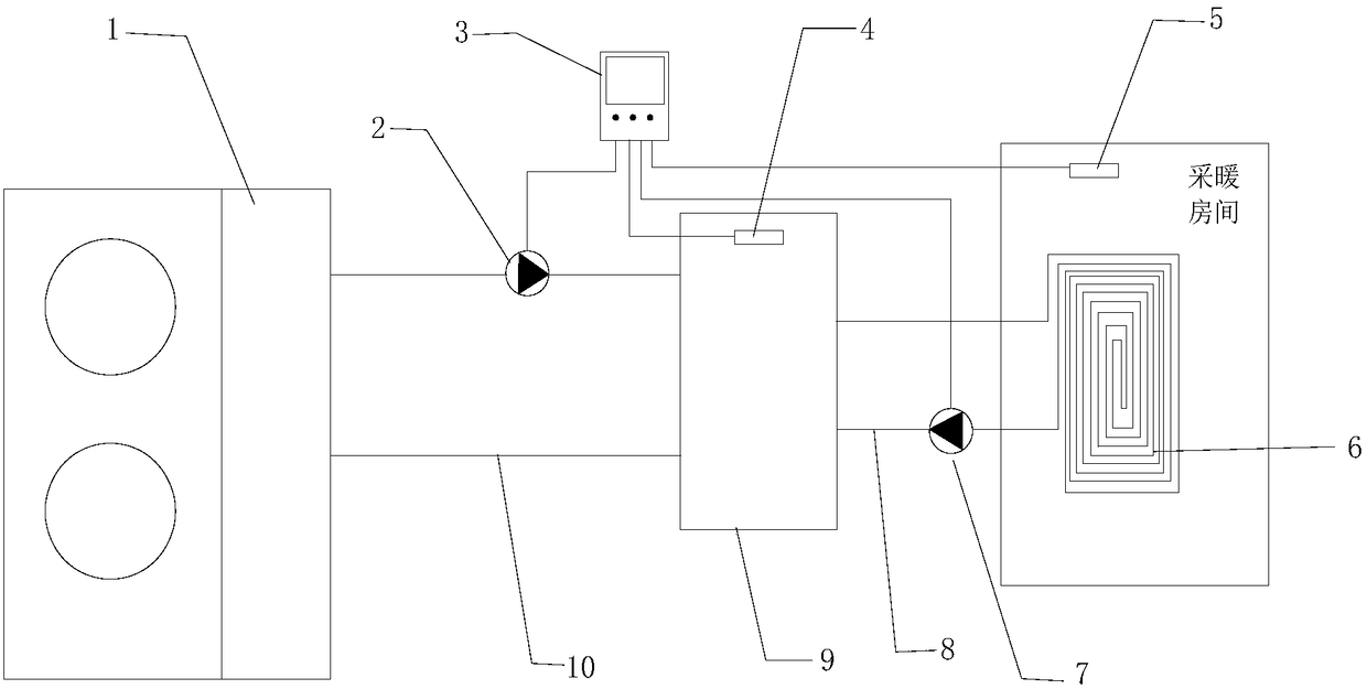
[0062] Such as figure 1 As shown, the heat pump heating system of the present invention includes: heat pump heating unit 1, heat pump heating unit side water pump 2, controller 3, water temperature sensor 4, room temperature sensor 5, heating terminal 6, heating terminal side water pump 7 and buffer water tank 9.

[0063] A heat pump is a device that transfers heat energy from a low-level heat source to a high-level heat source, and it is also a new energy technology that has attracted much attention around the world. It is different from the familiar mechanical equipment that can increase potential energy - "pump"; heat pumps usually first obtain low-grade heat energy from natural air, water or soil, do work through electricity, and then provide people with energy that can be used high-grade thermal energy. Usually, the heat pump heating unit 1 provides a heat source for the heating circuit.

[0064] Such as figure 1 As shown, the heat pump heating unit 1, the side water p...

Embodiment 2

[0083] In this embodiment, in the buffer water tank 9 , the heat transfer medium in the heat pump heating unit side circuit 10 and the heating terminal side circuit 8 can perform sufficient heat exchange. But the above two circuits are separated from each other, the heat transfer medium in the heat pump heating unit side circuit 10 and the heating end side circuit 8 are separated from each other in the buffer water tank 9, but the circuits on both sides are fully heat exchanged through the heat conduction device.

[0084] At this moment, the heating circuits on both sides of the buffer tank 9 are independent of each other. The heat pump heating unit 1 raises the temperature of the heat transfer medium in the side circuit 10 of the heat pump heating unit to the highest value of the predetermined temperature of the circuit and then stops working, and the buffer water tank 9 makes the heat transfer medium in the side circuit 10 of the heat pump heating unit slowly transfer heat to...

Embodiment 3

[0088] A heat pump heating method of the present invention is implemented on the heat pump heating system described in Embodiment 1 or 2.

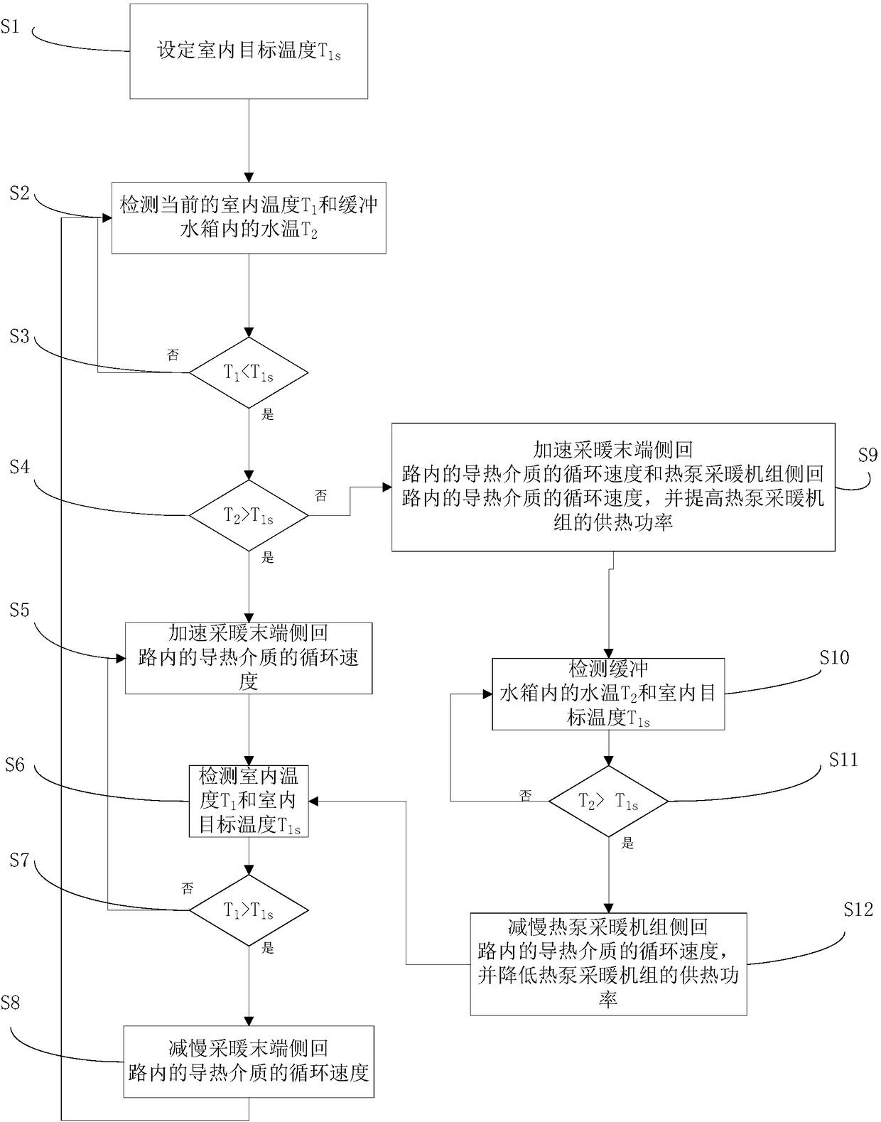
[0089] Such as figure 2 Shown:

[0090] Step S1, set indoor target temperature T 1s ;

[0091] Step S2, detecting the current indoor temperature T 1 and the water temperature T in the buffer tank 9 2 ;

[0092] Step S3, judging the indoor target temperature T 1s and the current room temperature T 1 relationship, when T 1 1s then execute step S4, otherwise continue to execute step S2;

[0093] Step S4, judging the water temperature T in the buffer water tank 9 2 and indoor target temperature T 1s relationship, when T 2 > T 1s then execute step S5, otherwise execute step S9;

[0094] Step S5, accelerating the circulation speed of the heat transfer medium in the heating terminal side loop 8;

[0095] Step S6, detecting the indoor temperature T 1 and indoor target temperature T 1s ;

[0096] Step S7, judging the indoor temper...


PUM


Abstract

The invention discloses a heat pump heating system and a heat pump heating method. The heat pump heating system comprises a buffer water tank and a controller. One side of the buffer water tank is connected with a heat pump heating unit to form a heat pump heating unit side loop, and the other side is connected with a heating tail end to form a heating tail end side loop. The controller is used tocycling speed of a heat-conducting medium in the pump heating unit side loop and the heating tail end side loop. The invention also discloses a heat pump heating method which uses value relations ofindoor target temperature, current indoor temperature, and water temperature of the buffer water tank to control circulation speed of the heating tail end side loop and the heat pump heating unit sideloop. The system and the method reduce start frequency of the heat pump unit, noise of the heat pump heating system is reduced, and energy-saving effect is substantial. Indoor temperature would not rapidly reduce or rise in a heating process, and user comfort level is improved.

Description

technical field [0001] The invention belongs to the field of heat pump heating, and in particular relates to a heat pump heating system and a heat pump heating method. Background technique [0002] At present, the common heating methods are as follows: coal heating, electric heating, gas heating, solar heating, heat pump heating. Based on the analysis of the above heating methods, with the tendency of national policies and the people's increasing concern for environmental protection, coal heating methods will gradually fade out of the heating field; electric heating and gas heating methods are also beyond the national policy support due to their high operating costs. Scope; solar heating method, the operating cost is low, but this heating method is too affected by weather changes, in order to ensure its use effect, sometimes electric auxiliary heat is added as an auxiliary heat source in the early design stage, and it is used as an alternative heat source for heating in rain...

Claims


Application Information

Patent Timeline
IPC IPC(8): F24D3/18F24D19/10
CPCF24D3/18F24D19/1039F24D2200/12F24D2220/042Y02B30/12
Inventor 王保森杨磊陈炳泉郑晓峰
Owner QINGDAO HAIER NEW ENERGY ELECTRIC APPLIANCE
Why Eureka
Try Eureka